
Engine cooling system
All vehicles covered in this manual use a hermetically sealed engine cooling system with thermostatically controlled coolant circulation (pic. 1.1) Coolant is circulated through the engine by a centrifugal pump mounted on the front side of the cylinder block. Coolant flows around each cylinder and flows to the rear of the engine. It then travels through channels in the cast cylinder head and cools the intake and exhaust valve ports, the spark plug area, and the exhaust valve guides.
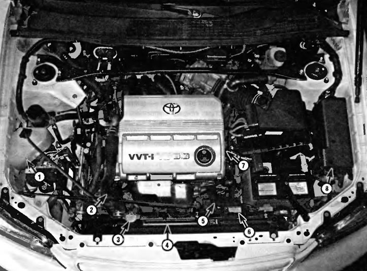
Pic. 1.1. Typical arrangement of elements of the cooling system (VG engine shown, similar for four-cylinder engine)
1 - Expansion tank
2 - Upper radiator hose
3 - Radiator cap
4 - Radiator
5 - Lower radiator hose
6 - Cooling fans
7 - Thermostat (approximate installation location shown)
8 - Box of fuses and relays
The paraffin-filled thermostat is located in a suitable housing near the front of the engine (pic. 1.2). During the warm-up phase, a closed thermostat prevents coolant from passing through the radiator. When the engine reaches normal operating temperature, the thermostat opens and the hot coolant can pass through the radiator where it is cooled before returning to the engine.
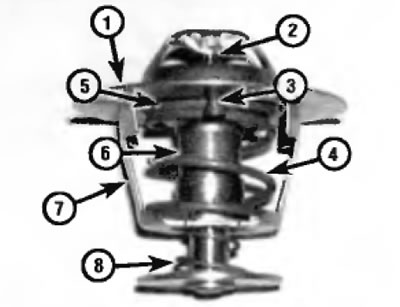
Pic. 1.2 Typical thermostat
1 - Flange
2 - Piston
3 - Overflow valve
4 - Valve spring
5 - Valve seat
6 - Valve
7 - Frame
8 - Secondary spring
The cooling system is sealed with a sealed radiator cap. This allows the boiling point of the coolant to be raised, and a higher boiling point allows the cooling efficiency provided by the radiator to be increased. If the pressure in the system exceeds the actuation value of the safety valve in the cap, the spring-loaded valve opens and coolant can flow through the overflow line to the expansion tank. As the system cools, excess coolant is automatically drawn from the reservoir back into the radiator.
The expansion tank serves as a reservoir from which fresh coolant is added to the cooling system to maintain the correct fluid level and as a reservoir for receiving overheated coolant.
This type of cooling system is called «closed system», because the coolant that escapes from the sealed cap is stored and reused.
Heating system
The heating system includes a blower fan and a heater radiator located in the heater housing, inlet and outlet hoses connecting the heater radiator to the engine cooling system, as well as a heater / air conditioner control panel on the front panel. Hot coolant circulates through the heater core. When the heating mode is activated, the damper opens, opening the passage from the heater housing to the vehicle interior. The fan switch on the control panel activates an electric fan that blows air through the heater core where it is heated.
Air conditioning system
The air conditioning system consists of a condenser mounted in front of the radiator, an evaporator mounted next to the heater radiator under the front panel, a compressor mounted on the engine, a dryer receiver that contains a high pressure relief valve, and pipelines connecting all of these elements.
The blower fan forces the warmer air from inside the car through the evaporator radiator, transferring heat from the air to the refrigerant. The liquid refrigerant is converted to low pressure vapor with heat extraction at the evaporator outlet. The compressor circulates the refrigerant through the system by forcing the heated refrigerant through the condenser where it is cooled and then circulated back to the evaporator.
Some models are equipped with an optional (installed at the request of the client) automatic air conditioning system. With this system, you select the desired interior temperature with a button on the control panel, similar to setting the temperature on a home heating/cooling thermostat, and the system automatically adds the correct mixture of cool or warm air to maintain that temperature. The system is equipped with sensors that detect both the interior temperature and the outside temperature.