
Note. These operations are performed only on models produced before 2001
Examination
Remove the air filter housing and air intake duct.
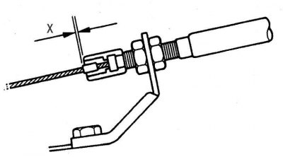
Pic. 9.11. Measuring the distance between the end of the cable sheath and the stopper on the throttle cable: X = 0–1 mm
The assistant should fully press and hold the accelerator pedal, at this time measure the distance X (pic. 9.11) between the edge of the cable sheath and the stopper on the cable. If the distance is 0–1 mm, then the cable is adjusted correctly, otherwise, adjust the cable.
Adjustment
The assistant should press and hold the accelerator pedal all the way, at this time, loosen the lock nut and, turning the adjusting nut, adjust the position of the cable sheath so that the distance between the end of the cable sheath and the stopper on the cable is within 0–1 mm.
Tighten the lock nut, re-measure the distance between the edge of the cable sheath and the stopper on the cable, and check that the throttle opens fully when the accelerator pedal is fully depressed.
Replacement
Loosen the locknut and remove the cable sheath from the throttle assembly bracket.
Disconnect the cable from the throttle sector.
Disconnect the cable sheath from the bracket on the gearbox.
Following the cable down, determine the place of its entry into the gearbox housing. Turn out a bolt supporting a cable at the demanded level.
Drain the transmission fluid from the transmission, remove the sump and filter.
On single drive axle models from 1996 to 1998, remove the two bolts and remove the bracket that supports the transmission fluid pipes. Disconnect the pipes from the gearbox.
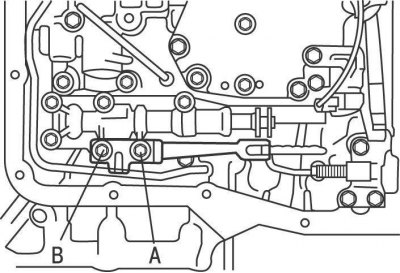
Pic. 9.12. Arrangement of bolts of fastening of a spring of a clamp on all-wheel drive models: A - bolt, 14 mm; B - bolt, 37 mm
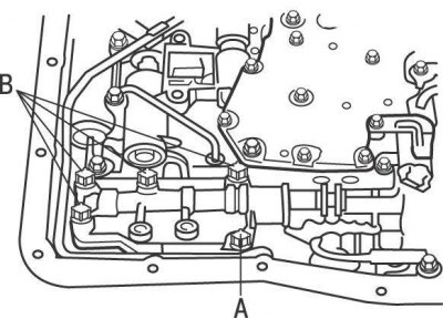
Pic. 9.13. The location of the mechanical valve mounting bolts on all-wheel drive models: A - bolt, 22 mm; B - bolt, 37 mm
On all-wheel drive models, remove the two bolts and remove the detent spring (pic. 9.12). Single drive axle models have only one bolt installed. On all-wheel drive models, remove the five bolts and remove the mechanical valve (pic. 9.13).
On 1996 through 1998 models, disconnect all electrical connectors from the solenoids.
On 4WD models, remove the bolt, release the clip, and use a large screwdriver to pry out all eight oil pipes.
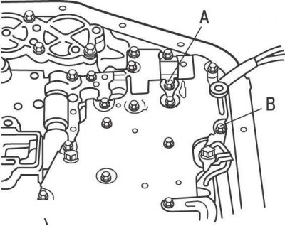
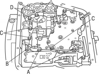
Pic. 9.14. The location of the bolts that must be removed before removing the small oil pipe on four-wheel drive models: A - bolt, 39 mm; B - bolt, 43 mm
On all-wheel drive models, unscrew the bolts securing the electrical connector, release the retainer and remove the small oil tube (pic. 9.14).
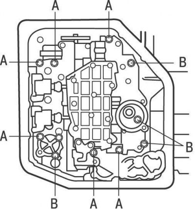
Pic. 9.15. Location of valve body mounting bolts on 2WD models from 1996 to 1998: A - bolt, 20 mm; B - bolt, 30 mm; C - bolt, 55 mm
Pic. 9.16. Location of valve body mounting bolts on 2WD models from 1998 to 2001: A - bolt, 20 mm; B - bolt, 28 mm; C - bolt, 50 mm
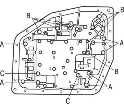
Pic. 9.17. Location of valve body bolts on 4WD models from 1996 to 2001: A - bolt, 22 mm; B - bolt, 32 mm; C - bolt, 43 mm; D - 55 mm
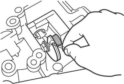
Pic. 9.18. Disconnecting the throttle control cable from the cam on the valve body
Remove the valve body mounting bolts (pic. 9.15, 9.16, 9.17). Separate the valve body from the transmission and disconnect the throttle control cable from the cam on the valve body (pic. 9.18).
Install in the reverse order of removal, taking into account the following.
After assembling the gearbox, fill it with transmission fluid.
If a new cable is to be installed, attach the stopper to it as follows.
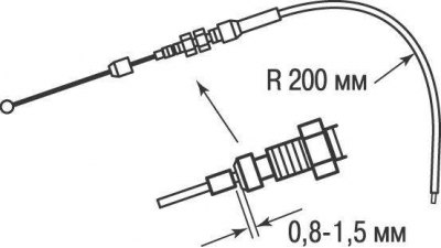
Pic. 9.19. Installing the Stopper on the New Throttle Cable
Bend the end of the cable on the side of the throttle assembly along a radius of 200 mm. Pull the cable out of the sheath until there is slight resistance, then attach the stopper to the cable at a distance of 0.8-1.5 mm from the edge of the cable sheath (pic. 9.19).
Connect the cable to the throttle sector and fix the cable sheath to the bracket, then adjust.