
With a small gap, the valve timing is disturbed, compression worsens, engine power decreases, engine operation becomes uneven. In some cases, the valves can be deformed and burn out.
If the gap is too large, mechanical knocking occurs, the valve timing is disturbed. Due to a decrease in the duration of the open state of the valves and poor ventilation of the cylinders, engine power is reduced. Engine performance becomes uneven.
For proper adjustment of the valves, they must be well lapped, the clearance in the guide bushings must not exceed the allowable limit, and the end of the valve stem mating with the rocker must not have cold hardening.
The clearance in the timing mechanism is checked and adjusted during maintenance, see section "Maintenance" and after repair, as well as in the presence of noise in the operation of the valve mechanism.
The clearance is checked and adjusted when the engine is warm. The engine can be considered warm after a car run of 10-15 km and with the temperature gauges on the control panel in the middle position.
Engines with rocker arms or levers
Attention: This describes checking and adjusting the gap in a 1.3 liter petrol engine from 8/84 onwards. Features of clearance adjustment for engines with a working volume of 1.3 liters up to 7/84 of release and engines with a working volume of 1.6 liters (4A-L,4A-LC) are described separately. Designation of engines.
Examination
Remove the block head cover.
Set the piston of the first cylinder to TDC.
To rotate the crankshaft, engage fifth gear and move the vehicle on a level surface. There is another possibility of turning the crankshaft. Raise one of the front wheels, engage fifth gear and turn the wheel by hand.
Check if the levers of the first cylinder are not pressed. They should have some clearance at the point of contact with the valve. The levers of the fourth cylinder must be pressed against the valve. If this condition is not met, then it is necessary to turn the crankshaft a full turn.
To check up a backlash at specified on fig. valves with a feeler gauge between the lever and the camshaft and adjust if necessary. The specified gap values are shown in the table. EX: exhaust valve IN: intake valve.
1.3L Engines for 7/84, 1.6L Engines (4A-L, 4A-LC)
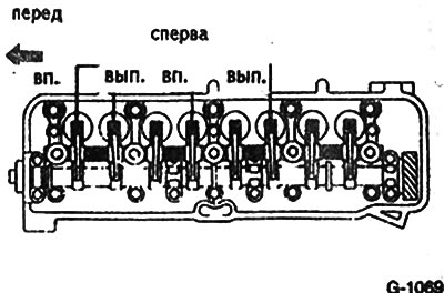
Check the clearance of the ones shown in Fig. G-1069 valves between the rocker arms and the ends of the valve stems and adjust if necessary. The specified gap values are shown in the table.
The feeler gauge should bite slightly when checking clearances. Otherwise, the clearance must be adjusted.
Rotate the engine a full turn until the marking on the pulley matches the marking on the timing cover.
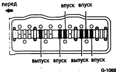
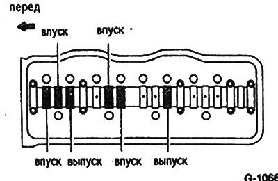
To check up a backlash at specified on fig. G-1068 valves between rocker arms and camshaft and adjust if necessary. The specified gap values are shown in the table.
Engines with displacement 1.3 l up to /84 year of manufacture 1.6 l (4A-L, 4A-LC)
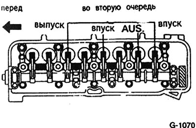
Check the clearance of the ones shown in Fig. G-1070 valves with a feeler gauge between the rocker arms and the ends of the valve stems and adjust if necessary. The specified gap values are shown in the table.
The feeler gauge should bite slightly when checking clearances. Otherwise, the clearance must be adjusted.
Adjustment
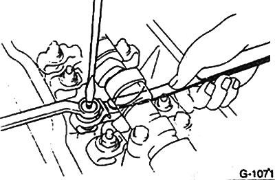
If the gap is not as specified, back the locknut about 1 turn with a ring wrench while holding the adjusting screw from turning with a screwdriver.
Turn the adjusting screw with a screwdriver to adjust the clearance in the valve mechanism.
Lock the adjusting screw with a nut.
Check the valve clearance again.
In the same way, adjust the clearances in all valves.
Attention: It is advisable to mark with chalk valves for which the gaps have already been adjusted.
After adjusting the valves, check the tightness of the rocker arm bolts.
Install the cylinder head cover.
Engines with cylindrical pushrods
Attention: This describes the check and adjustment of clearances for gasoline engines with a displacement of 1.6 liters (4A-PE). Features of adjusting clearances for other engines with a displacement of 1.6 liters with four-valve cylinder heads and for a diesel engine with a displacement of 1.8 liters are described separately.
Examination
Remove cylinder head cover.
Set the piston of the first cylinder to TDC.
To crank the engine, engage a gear and move the vehicle on a level surface. There is another possibility of cranking the engine. It is necessary to lift one of the five wheels, engage fifth gear and turn the wheel by hand.
In this position, the cylindrical pushers of the first cylinder should be free and the pushers of the fourth cylinder should be pressed with cams. If this condition is not met, then the crankshaft must be rotated one revolution.
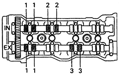
To check backlashes of valves at specified on fig. valves between the tappets and the camshaft and adjust if necessary. The specified gap values are shown in the table.
Diesel working volume 1.8 l
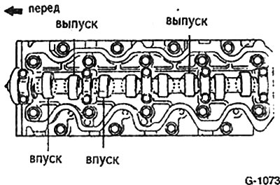
To check backlashes of the valvate mechanism at specified on fig. G-1073 valves between tappets and camshaft and adjust if necessary. The specified gap values are shown in the table.
The feeler gauge should bite slightly when checking clearances.
Rotate the engine one revolution until the marking on the pulley matches the marking on the timing cover.
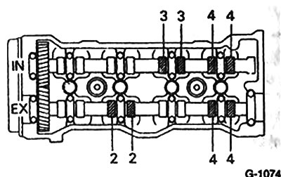
Check the clearance of the ones shown in Fig. valves between the tappets and the camshaft and adjust if necessary. The specified gap values are shown in the table.
Diesel working volume 1.8 l
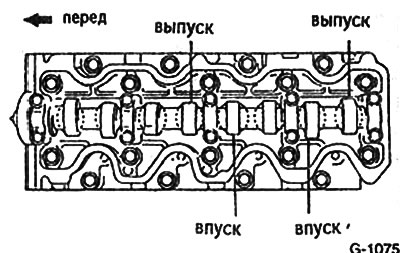
To check up a backlash at specified on fig. G-1075 valves between tappets and camshaft and adjust if necessary. The specified gap values are shown in the table.
The feeler gauge should bite slightly when checking clearances.
When checking the gaps, it is necessary to select the thickness of the feeler gauge until the actual gap value is determined. Record the measured gap value.
Adjustment
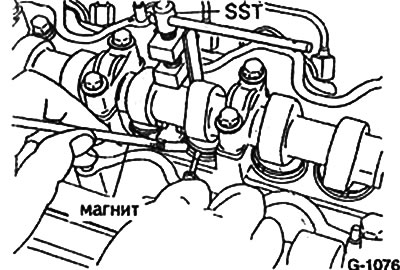
The clearance in the valve mechanism is adjusted by selecting adjusting washers. To do this, the cylindrical pushers are pressed down.
Attention: Special clamps can be used for this purpose, in particular SST09248-64010 (for diesel) and SST 09248-55010 (for engines 4A-GE, 4AGEL, 4A-F, 4A-FE).
Press the cylindrical pusher, remove the adjusting washer with a magnet and insert another one instead.
Determination of shim thickness
Measure the thickness of the removed shim with a micrometer. Record the result.
To determine the thickness of a newly installed shim, the formula is used
N=T+ (A - S), Where
N = new washer thickness
T = thickness of washer removed
A = measured valve clearance
S = gap, see table
The thickness of the shim is engraved on its underside.
Insert a new shim. Washer thicknesses are in the range of 2.5-3.3 mm with an interval of 0.05 mm (diesel in the range of 2.2-3.4 mm).
Thus, adjust all valves.
Install and bolt the cylinder head cover.
Valve clearances
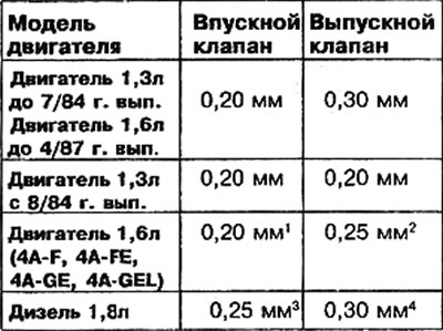
1) setting value; control value 0.15-0.25 mm.
2) setting value; control value 0.20-0.30 mm.
3) setting value; control value 0.20-0.30 mm.
4) setting value; control value 0.25-0.35 mm.