



Camshafts and valve lifters
Removal
1. Drain the coolant (see Chapter 1B).
2. Remove the valve cover as described in paragraph 4.
3. Remove the timing belt and camshaft sprocket as described in paragraph 7.
4. Loosen the mounting bolt and remove the crankshaft position sensor from the rear of the cylinder head (see Figure 10.4).
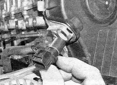
Figure 10.4. Removing the camshaft position sensor.
5. Loosen the two mounting bolts and remove the brake booster vacuum pump from the cylinder head. Remove the two O-rings (see Figure 10.5, a-c).
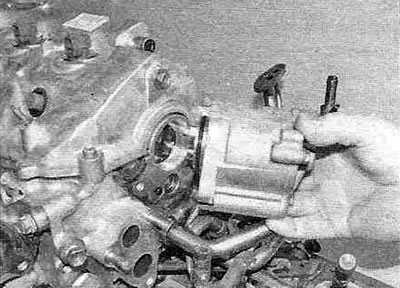
Figure 10.5,a. Remove the brake booster vacuum pump from the rear of the cylinder head...
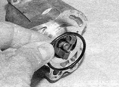
Figure 10.5, b....remove the large sealing ring...
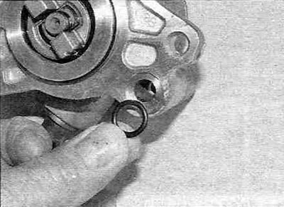
Figure 10.5, c....and a small sealing ring.
6. Loosen the mounting bolts and remove the injector fuel drain line.
7. Loosen the mounting bolts and carefully separate the camshaft oil seal housing from the cylinder head (see Figure 10.7).
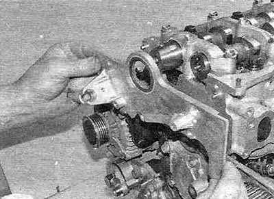
Figure 10.7. Removing the camshaft oil seal housing from the cylinder head.
Remove the old oil seal from the bore.
8. Mark the position of each camshaft bearing cap on the cylinder head to prevent possible assembly errors.
9. Gradually loosen the camshaft support cover mounting bolts in the sequence shown in the figure 10.9,a, then remove the camshaft support caps, camshafts and camshaft bed (see Figure 10.9, b-g).
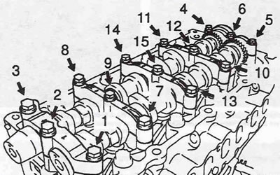
Figure 10.9,a. Sequence of loosening the camshaft support cover bolts.
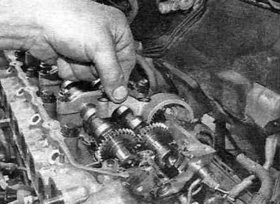
Figure 10.9,b. Remove the camshaft support covers...
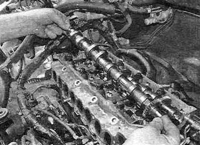
Figure 10.9, c....then pull out the camshafts...
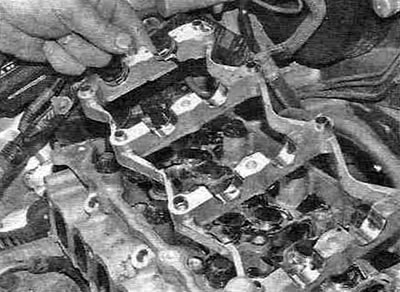
Figure 10.9, g....and the camshaft bed.
Warning. Failure to follow the bolt loosening sequence may result in damage to the cylinder head.
10. Using a magnet or suction cup, remove the valve lifters and their adjusting washers from the pilot holes and then stack them in the proper order to avoid assembly errors (see figure 10.10).
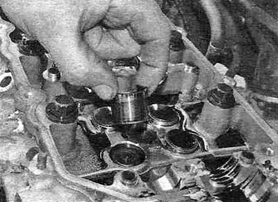
Figure 10.10. Removing the valve lifters.
11. Check the condition of the camshafts and valve lifters as described in chapter 2A.
Installation
12. Install the valve lifters and corresponding adjusting washers strictly in their places, having first lightly lubricated the drilling guides with engine oil. The pushers should turn easily with your fingers (see Figure 10.12).
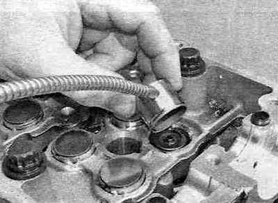
Figure 10.12. Install the valve tappets with the corresponding washers strictly in their places.
13. Install the camshaft bed into the cylinder head (see Figure 10.13).
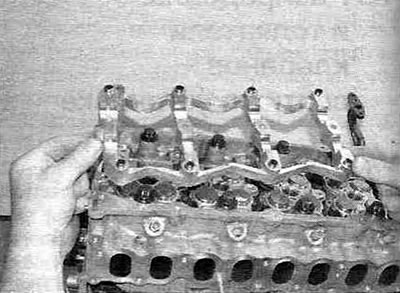
Figure 10.13. Install the camshaft bed into the cylinder head.
14. Lubricate the working surfaces of the bed and the bearing journals of the intake camshaft with engine oil and install the intake camshaft in its place at the front of the cylinder head (see figure 10.14,a,b). The camshaft must be installed so that the cams of cylinders No. 3 and No. 4 are directed downwards.
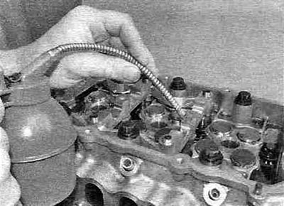
Figure 10.14,a. Lubricate the working surfaces of the camshafts with engine oil...
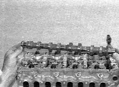
Figure 10.14, b....then install the intake camshaft into the cylinder head.
15. Lubricate the working surfaces of the bed and the bearing journals of the exhaust camshaft with engine oil and install the exhaust camshaft in its place in the rear part of the cylinder head, simultaneously aligning the TDC marks on the gears of both camshafts. TDC marks are applied on the inside of the gears (see Figure 10.15).
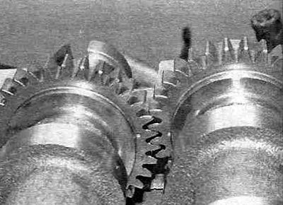
Figure 10.15. Before installing the bearing caps, align the TDC marks on the camshaft gears.
16. Clean the mating surface of the support cover No. 5 and apply sealant as shown in the figure 10.16.
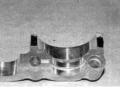
Figure 10.16. Apply sealant to camshaft support cover No. 5.
17. Install all support covers strictly in their places (see Figure 10.17,a), then tighten the bolts of their fastening in stages to the prescribed torque in the sequence shown in the figure 10.17,b.
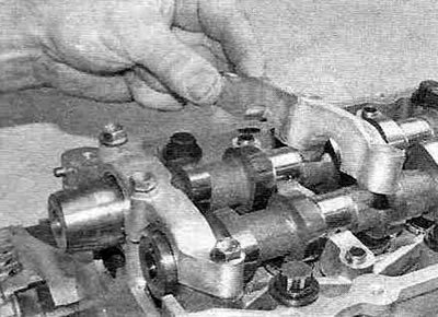
Figure 10.17,a. Installing the camshaft support covers.
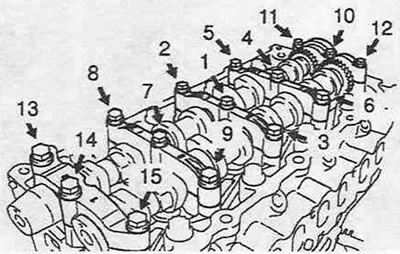
Figure 10.17, b. Sequence of tightening the bolts securing the camshaft support covers.
18. Check and adjust the valve clearances as described in chapter 1B.
19. Clean the mating flange of the seal housing and apply a 2-4 mm wide bead of sealant as shown in the figure 10.19.
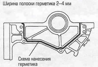
Figure 10.19. Apply sealant to the camshaft oil seal housing as shown.
Install the housing and tighten the mounting bolts to the specified torque.
20. Install the new oil seal into the housing as follows: place the new oil seal onto the camshaft, then use a piece of metal pipe to press it flush with the outer edge of the mounting hole.
21. Clean the semicircular plugs from any remaining sealant and fill the grooves with new sealant, then install them into the cylinder head.
22. Install the injector fuel drain line and tighten the union bolts to the specified torque.
23. Press new sealing rings into the brake booster vacuum pump housing, then install the pump, aligning the guide tabs of the booster mating flange with the grooves of the camshaft. Install the mounting bolts and tighten them to the specified torque.
24. Install the timing belt and camshaft sprocket as described in paragraph 7.
25. Install the valve cover as described in paragraph 4.