



Cylinder head
Caution: Allow the engine to cool completely before starting the procedure.
Removal
1. Drain the coolant (see Chapter 1B).
2. Remove the intercooler (see chapter 4B) and top engine covers.
3. As described in paragraph 7, remove the timing belt and camshaft sprocket. Also unscrew the mounting bolts and remove the inner triangular timing belt cover (see Figure 11.3).
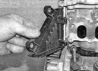
Figure 11.3. Removing the inner triangular timing belt cover.
4. Remove the turbocharger as described in chapter 4B.
5. Loosen the mounting nuts and remove the exhaust manifold from the cylinder head. Remove the bushings and gasket.
6. Loosen the mounting bolt and remove the crankshaft position sensor from the rear of the cylinder head.
7. If installed, unscrew the mounting bolts and remove the cover from the fuel injection pump and remove the insulator.
8. Disconnect the wiring connectors and vacuum hose, then unscrew the mounting bolts and remove the intake air duct and throttle body together with the gasket (see figure 11.8,a,b).
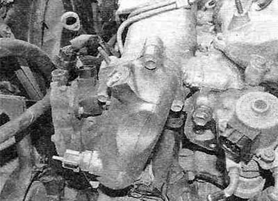
Figure 11.8,a. Unscrew the mounting bolts...
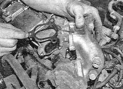
Figure 11.8, b....and remove the intake air duct together with the throttle body and gasket.
9. Loosen the fuel rail mounting bolts. This must be done in order to free up space for removing the intake manifold.
10. Loosen the mounting bolts and nuts and remove the intake manifold together with the gasket (see figure 11.10, a, b).
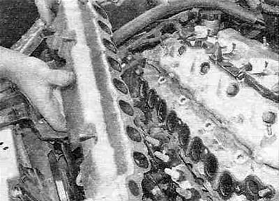
Figure 11.10,a. Removing the intake manifold...
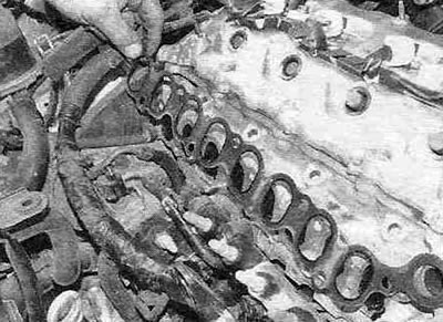
Figure 11.10, b....and gaskets.
11. Loosen the mounting bolts and remove the timing belt cover bracket.
12. Disconnect the positive crankcase ventilation valve hose.
13. Disconnect the cooling system outlet pipe and remove the gasket (see figure 11.13,a,b).
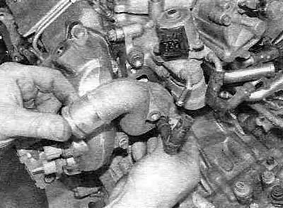
Figure 11.13,a. Loosen the mounting bolts and remove the cooling system outlet pipe...
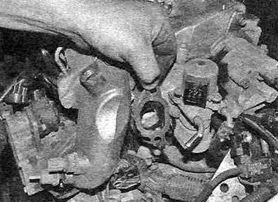
Figure 11.13, b....and remove the gasket.
14. Loosen the mounting bolts and remove the fuel rail (see Figure 11.14).
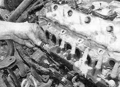
Figure 11.14. Removing the fuel rail.
15. If necessary, loosen the mounting bolts and remove the coolant temperature sensor.
16. Remove the exhaust gas recirculation valve by unscrewing one bolt and two nuts (eGR valve) (see figure 11.16,a,b).
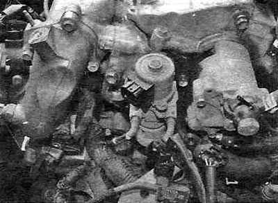
Figure 11.16,a. Location of the exhaust gas recirculation valve (EGR valves).
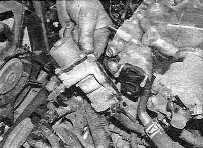
Figure 11.16,b. Removing the exhaust gas recirculation valve.
17. Loosen the two mounting bolts and remove the brake booster vacuum pump from the end of the cylinder head (see Figure 11.17).
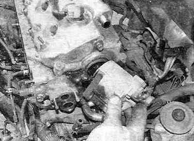
Figure 11.17. Removing the brake booster vacuum pump.
Remove the two O-rings.
18. If an additional heater is installed at the end of the head, remove the caps from its terminals and unscrew the three nuts securing the wires. Unscrew and remove the heater plugs.
Note: Additional heaters are only installed on models designed for use in cold climates.
19. Loosen the clamps and disconnect the fuel hose and oil cooler hose.
20. Loosen the mounting bolts and remove the fuel drain line shut-off valve, tube and gasket.
21. Unscrew the union bolts and remove the injector fuel drain line.
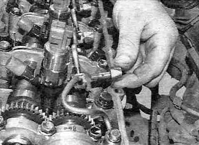
Figure 11.21,a. Unscrew the union bolts...
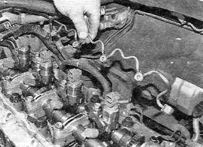
Figure 11.21, b....and remove the injector drain line.
22. Remove the injectors as described in chapter 4B. This procedure involves removing the valve cover.
23. Loosen the mounting bolts and remove the camshaft oil seal housing from the cylinder head (see Figure 11.23).
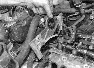
Figure 11.23. Removing the camshaft oil seal housing.
Remove the old seal from the housing.
24. Mark the position of all camshaft bearing caps on the cylinder head to eliminate possible errors during assembly.
25. Gradually loosen the camshaft support cover mounting bolts in the sequence shown in Figure 10.9,a, and remove the covers, then take out the camshafts and remove the camshaft bed.
Warning. Failure to follow the sequence for loosening the camshaft cover mounting bolts may result in damage to the cylinder head.
26. Loosen the cylinder head mounting bolts step by step, strictly following the sequence shown in the figure 11.26, then remove the bolts together with the washers.
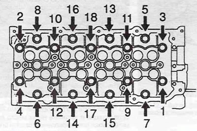
Figure 11.26. Sequence for loosening the cylinder head bolts.
Warning. Failure to follow the sequence of loosening the cylinder head mounting bolts may result in cracks in the housing and distortion of the head mounting flange.
27. Make sure all wiring connectors are disconnected, then carefully, lifting the head straight up, remove it from the cylinder block guide pins and install it on a work bench.
28. Remove the gasket from the cylinder block. Don't throw it away - it will come in handy to determine the thickness of the new gasket.
Installation
29. Before installation, the mating surfaces of the head and block must be dry and absolutely clean. Remove traces of old gasket and carbon deposits with a hard plastic or wooden scraper. Clean the carbon deposits from the pistons as well. Be especially careful when cleaning the head/block surface, as the aluminum alloy is easily damaged. Carbon deposits should not get into the oil and water passages, especially the oil passages, as they can block the supply of lubricant to the rubbing surfaces of the engine. Plug the holes with tape and paper plugs.
30. The mating surfaces of the head and block must not have cracks, cavities or nicks. Minor defects can be removed with sandpaper.
31. If there is a suspicion that the mating surface of the head is warped, check it with a steel ruler (for curvature limits, see Specifications). Please note that the cylinder head cannot be ground.
32. Tap the threads of the holes for the mounting bolts using a suitable tap. Remove all traces of oil and water from the threaded holes by carefully rinsing them with solvent and blowing them out with compressed air.
33. In diesel engines, a situation may arise where the piston crowns collide with the valve heads and damage them. This occurs when the camshaft rotates without the timing belt, resulting in the crankshaft position corresponding to TDC. Therefore, when installing the cylinder head, the piston of cylinder #1 should be in a position other than TDC. Rotate the crankshaft approximately 90° counterclockwise as described previously, which corresponds to the mid-stroke of all four pistons.
34. Inspect the old gasket and locate the manufacturer's identification mark on it. It is made in the form of cutouts on the front edge of the gasket (see Figure 11.34).
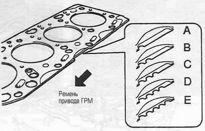
Figure 11.34. Cylinder head gasket identification cutouts.
Before replacing the pistons, the new cylinder head gasket must have the same identification mark as the old gasket.
35. If you have replaced the pistons during an engine overhaul, before purchasing a new cylinder head gasket, to determine its thickness, you need to measure the piston protrusion as follows. Set the piston of cylinder No. 1 to TDC. Using a dial indicator or depth micrometer, measure the distance the piston protrudes above the cylinder block mating surface (see Figure 11.35).
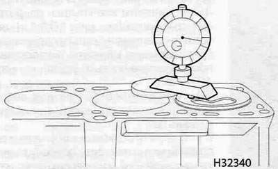
Figure 11.35. Measuring the piston protrusion using a dial indicator.
Repeat the measurement on the three remaining cylinders and record the maximum value. Using the maximum piston protrusion value as a basis, use it to determine the required shim thickness (see table).
| Piston protrusion | Number of cutouts in the gasket (index) | Gasket thickness |
| 0.165-0.220 mm | 1 (A) | 0.85-0.95 mm |
| 0.220-0.270 mm | 2 (B) | 0.90-1.00 mm |
| 0.270-0.320 mm | 3 (C) | 0.95-1.05 mm |
| 0.320-0.370 mm | 4 (D) | 1.00-1.10 mm |
| 0.370-0.425 mm | 5 (E) | 1.05-1.15 mm |
36. Using a hacksaw, cut off the heads of two old cylinder head mounting bolts and then use a hacksaw to cut a slot in the smooth part of each bolt for the appropriate screwdriver. These bolts will be used as guides when installing the head.
37. Screw the manufactured guides into the outer rear holes of the cylinder block and place the new gasket, aligning it with the mounting pins on the cylinder block. The gasket must be laid in such a way that the TOP (top) mark and the digital index are on top.
38. With the help of an assistant, install the head strictly on the cylinder block, ensuring that the block locating pins are aligned with the recesses in the head. Before lowering the head completely onto the block, make sure the gasket is not displaced from its position.
39. Lubricate the threads, bottoms of the bolt heads and washers with engine oil, then carefully insert each bolt into its corresponding hole and tighten it finger tight. Only use the following to secure the head: new bolts, as the old ones have stretched out during tightening and will not provide the required tightening torque when reused. Note that the bolts in the outer rows are longer than the bolts in the inner rows.
40. Unscrew the guides you made and insert the two remaining cylinder head mounting bolts in their place, then tighten them by hand.
41. Gradually tighten the mounting bolts in the sequence shown in the figure 11.41, until the prescribed time Torque specifications, make the first pass.
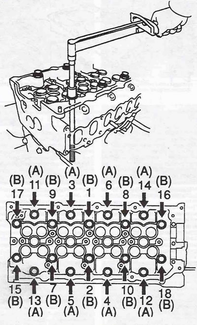
Figure 11.41. Cylinder head bolt tightening sequence:
A = 160 mm;
B = 104 mm.
42. In the same sequence, perform the 2nd pass, tightening the mounting bolts to the specified value Specifications angle.
Note: When tightening the bolts, it is recommended to use a bevel gauge for more accurate results. If the tool is not available, mark the appropriate angles on the bolt heads and cylinder head with paint before tightening.
43. In the same sequence, perform the 3rd pass, tightening the mounting bolts to the specified value Specifications angle.
44. In the same sequence, perform the 4th pass, tightening the mounting bolts to the specified Specifications angle.
45. Install the camshaft bed into the cylinder head.
46. Lubricate the working surfaces of the bearings and the bearing journals of the intake camshaft with engine oil and install the intake camshaft in its place in the front part of the cylinder head (see figure 14,a,b). The camshaft must be installed so that the cams of cylinders No. 3 and No. 4 are directed downwards.
47. Lubricate the working surfaces of the bearings and the bearing journals of the exhaust camshaft with engine oil and install the exhaust camshaft in its place in the rear part of the cylinder head, simultaneously aligning the TDC marks on the gears of both camshafts. TDC marks are applied on the inside of the gears.
48. Clean the mating surfaces of camshaft support cover No. 5 and apply sealant as shown in the figure 11.48.
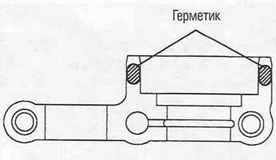
Figure 11.48. Apply sealant to the shaded areas of the surface of camshaft support cover No. 5.
49. Install all support covers strictly in their places (see Figure 10.17,a), then tighten the mounting bolts in stages to the specified torque, following the sequence shown in the figure 10.17,6.
50. Check and adjust the valve drive mechanism clearances as described in chapter 1B.
51. Clean the mating flange of the seal housing and apply a 2-4 mm wide bead of sealant as shown in the figure 10.19.
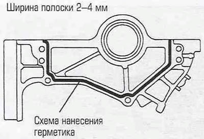
Figure 11.51. Apply sealant to the camshaft oil seal housing as shown.
Install the housing and tighten the mounting bolts to the specified torque.
52. Install the new oil seal into the housing as follows: place the new oil seal onto the camshaft, then use a piece of metal pipe to press it flush with the outer edge of the mounting hole.
53. Clean the semicircular plugs from any remaining sealant and fill the grooves with new sealant, then install them into the cylinder head.
54. Install the injectors as described in chapter 4B.
55. Install the injector fuel drain line and tighten the union bolts to the specified torque.
56. Install the fuel drain line shut-off valve, tube and gasket.
57. Install the fuel hose and oil cooler hose.
58. Where an additional heater is provided, install the spark plugs, connect the wires and put on the caps.
59. Press new sealing rings into the brake booster vacuum pump housing, then install the pump itself, aligning the guide tabs of the booster mating flange with the grooves of the camshaft. Install the mounting bolts and tighten them to the specified torque.
60. Install the EGR valve with a new gasket and tighten the mounting bolts to the specified torque.
61. Install the coolant temperature sensor.
62. Install the fuel rail, but do not tighten the mounting nuts at this stage.
63. Install the coolant outlet pipe with a new gasket and tighten the mounting bolts to the specified torque.
64. Install the positive crankcase ventilation valve hose.
65. Install the timing belt cover bracket and tighten the mounting bolts to the specified torque.
66. Install the intake manifold with a new gasket and tighten the mounting bolts and nuts to the specified torque (see Figure 11.66).
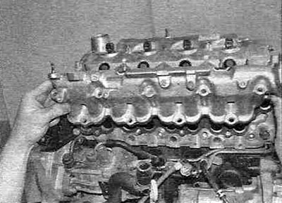
Figure 11.66. Installing the intake manifold.
67. Fully tighten the fuel rail mounting bolts to the specified torque.
68. Install the intake air duct and throttle body together with a new gasket and tighten the bolts and nuts to the specified torque. Connect the wiring connectors and vacuum hose.
69. If equipped, install the insulator and fuel pump cover and tighten the mounting bolts to the specified torque.
70. Install the camshaft position sensor.
71. Install the exhaust manifold with a new gasket. Install the exhaust manifold bushings and bolts and tighten them to the specified torque.
72. Install the turbocharger as described in chapter 4B.
73. Install the timing belt and camshaft sprocket as described in paragraph 7. Also install the inner triangular timing belt cover.
74. Install the engine top covers and intercooler as described in chapter 4B.
75. Fill with coolant as described in chapter 1B. Start the engine and check for leaks.