



Timing Belt and Sprockets
1. The main function of the timing belt is to transmit torque to the camshafts, and it is also used to drive the fuel injection pump, water pump and oil pump. A slipping or broken belt while the engine is running will disrupt the valve timing, causing the pistons to collide with the valves and, consequently, serious engine damage.
2. Taking into account the above, it is necessary to regularly check the timing belt tension and its condition for damage and signs of wear.
Removal
3. Remove the intercooler (see chapter 4B) and the top engine covers, while simultaneously releasing the vacuum hose from the retainer (see Figure 7.3, a-c).
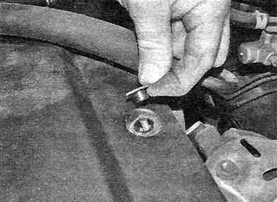
Figure 7.3,a. Loosen the fastening nuts...
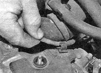
Figure 7.3, b....release the vacuum hose...
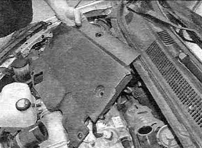
Figure 7.3, c....and remove the top engine cover.
4. Remove the glow plugs as described in chapter 5, to make it easier to turn the engine in the future.
5. Remove the accessory drive belt(s) as described in chapter 1B. Since space is limited, it is recommended to remove the right headlight (see chapter 12) and front bumper.
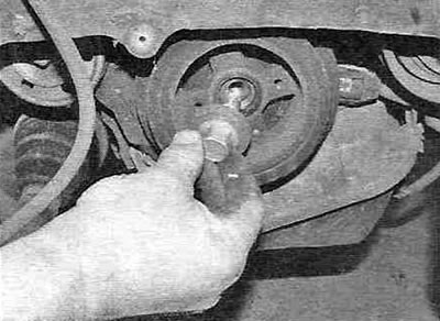
6. Remove the crankshaft pulley (see Figure 7.6, a-g).
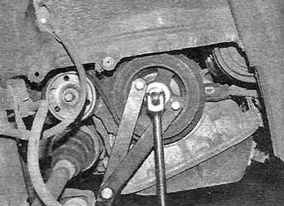
Figure 7.6,a. While holding the crankshaft from turning with a suitable device, loosen the crankshaft pulley mounting bolt.
 .
.
Figure 7.6, b. Unscrew the mounting bolt...
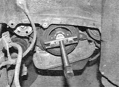
Figure 7.6, c....then, using a puller, remove the pulley from the crankshaft...
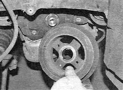
Figure 7.6, d....and remove it from the engine.
7. Loosen the mounting bolts and remove the upper timing cover from the cylinder head/valve cover (see figure 7.7).
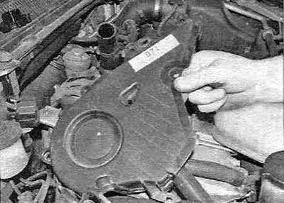
Figure 7.7. Removing the upper timing belt cover.
8. Loosen the mounting bolts and remove the alternator drive belt tensioner pulley, then loosen the mounting bolts and remove the lower timing belt cover from the cylinder block (see figure 7.8,a,6).
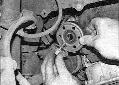
Figure 7.8,a. Loosen the mounting bolt and remove the generator drive belt tensioner pulley...
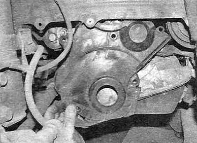
Figure 7.8, b....then unscrew the mounting bolts and remove the lower timing drive cover from the cylinder block.
Also remove the oil pump oil deflector plate, if present.
9. Remove the timing belt guide washer from the crankshaft (see Figure 7.9).
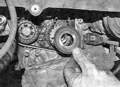
Figure 7.9. Removing the timing belt guide/washer from the crankshaft.
10. Unscrew the power steering pump mounting bolts together with the tensioner and move it to the side without disconnecting the hydraulic pipes (see Figure 7.10).
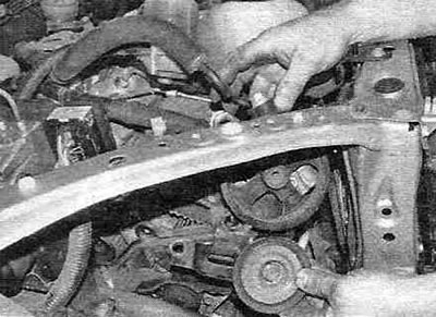
Figure 7.10. Unscrew the power steering pump mounting bolts together with the tensioner and move it to the side.
11. Raise the engine with a hydraulic jack, placing a piece of board between them, then remove the right engine mount (see paragraph 16) and, having unscrewed the mounting bolts, remove the support bracket from the engine. For better access through the headlight opening, also remove the support bracket (see figure 7.1 1,a-c).
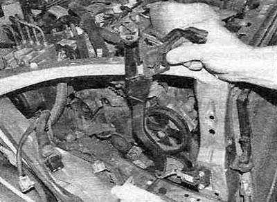
Figure 7.11,a. To improve access, unscrew the mounting bolts and remove the support bracket.
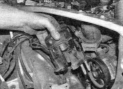
Figure 7.11,b. Removing the right upper engine mount from the inner casing.
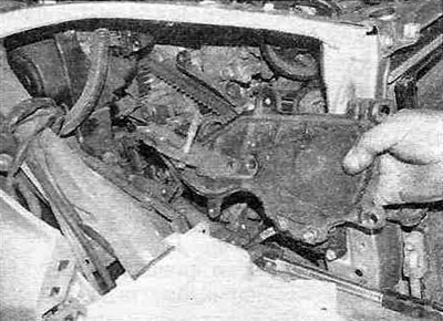
Figure 7.11, c. Removing the right lower support from the engine.
12. Set the piston of cylinder No. 1 to TDC of the compression stroke, as described in paragraph 3.
13. If the timing belt is to be reinstalled, mark its direction of rotation to avoid assembly errors.
14. Loosen the bolt and remove the timing belt spacer/guide located under the camshaft sprocket.
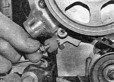
Figure 7.14. Removing the timing belt spacer/guide.
15. Gradually unscrew the two bolts and remove the tensioner (see figure 7.15, a, b).
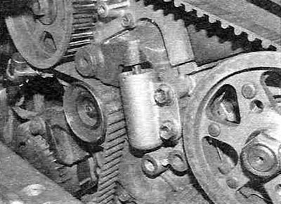
Figure 7.15,a. Unscrew the two bolts...
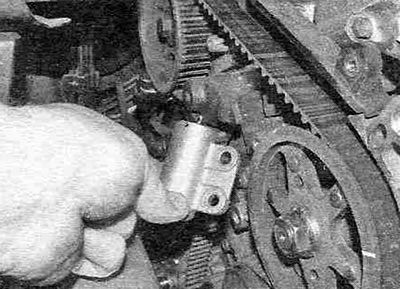
Figure 7.15, b....and remove the tensioner.
If necessary, also remove the idler pulley and tensioner arm.
16. Remove the timing belt from the camshaft sprockets, fuel injection pump, water pump, crankshaft and oil pump and remove it from the engine (see Figure 7.16).
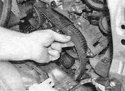
Figure 7.16. Removing the timing belt.
17. To remove the camshaft sprocket, you need to secure the camshaft by inserting a suitable lever into the sprocket hole, then unscrew and remove the central bolt. Using a puller, pull the sprocket off the exhaust camshaft and also remove the key (see Figure 7.17, a-c).
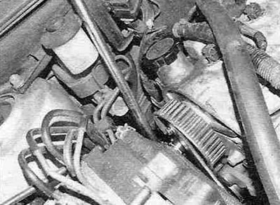
Figure 7.17,a. While holding the sprocket from turning, unscrew the central mounting bolt...
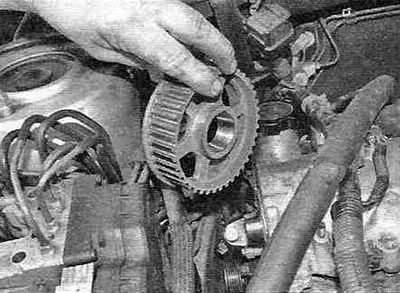
Figure 7.17, b....then remove the sprocket...
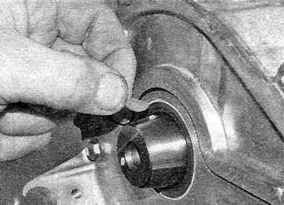
Figure 7.17, c....and remove the key.
It may not be possible to install the puller because the distance between the inner housing and the sprocket is too small. In this case, you can carefully pull off the sprocket using, for example, two screwdrivers.
18. Remove the sprocket from the crankshaft. If the sprocket is tight, use a suitable puller by inserting it into the bolt holes. Also remove the keys from the crankshaft (see figure 7.18,a,b).
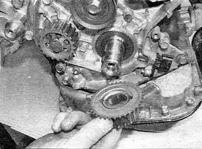
Figure 7.18,a. Remove the crankshaft sprocket...
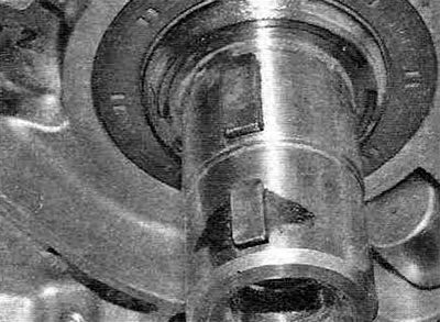
Figure 7.18, b....and remove the keys from the crankshaft.
19. Removing the fuel injection pump drive sprocket is described in chapter 4B. Secure the sprocket, loosen the mounting nut and, using a suitable puller, remove it from the shaft.
20. Loosen the mounting bolt and remove the tensioner roller from the cylinder block. If necessary, also remove the front tension roller.
Examination
Warning. The timing belt should not be folded, twisted or turned inside out. Do not allow it to come into contact with oil, coolant or fuel. Do not use timing belt tension to prevent shaft rotation when tightening sprocket mounting bolts. Do not rotate the crankshaft or camshaft more than a few degrees (only if necessary to align the teeth) with the belt removed.
21. Visually determine the degree of wear of the sprockets and tension rollers and, if necessary, replace them. Determine the condition of the tensioner as follows. Check the integrity of the internal seal - if oil leakage is evident, replace the tensioner. Place the tensioner on the workbench with the rod facing down and press on the body - the rod should not move. Measure the protruding part of the rod - if its value is more than 10.6 mm, replace the tensioner (see Figure 7.21).
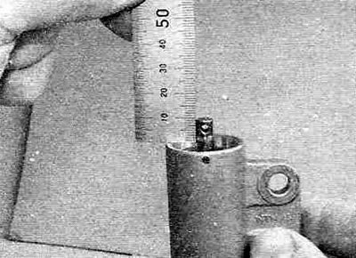
Figure 7.21. Measuring the protruding portion of the timing belt tensioner rod.
22. Inspect the timing belt and make sure there are no traces of coolant or oil. If the belt is contaminated, determine the cause of the contamination and eliminate it without proceeding to the next steps of the procedure. Inspect the belt for wear and damage, paying particular attention to the teeth (see Figure 7.22).
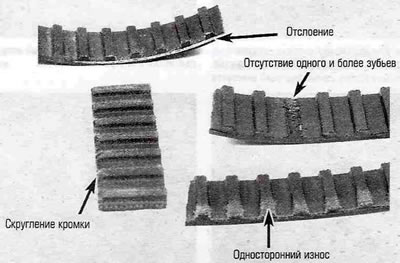
Figure 7.22. Check the timing belt for cracks and chipped teeth. One-sided wear indicates misalignment of the sprockets in the vertical plane (belt misalignment).
Warning. If the belt is in good condition and suitable for further use, it is very important that it is installed in its place during assembly in exactly the same position as it was before removal. Incorrect installation of the belt will lead to accelerated wear and, as a result, premature engine failure.
23. Replace the belt if you have any doubts about its condition. The price of a timing belt is incomparable to the cost of engine repairs caused by its breakage. In any case, if the car's mileage exceeds 60,000 km, replace the belt, regardless of its condition.
Installation
24. Make sure that the piston of cylinder No. 1 is at TDC of the compression stroke, as described in paragraph 3.
25. Install the tensioner pulley and tension rollers and tighten the mounting bolts to the specified torque.
26. If it was removed, install the fuel injection pump drive sprocket, referring to chapter 4B.
27. Install the key, then install the sprocket onto the crankshaft, using a piece of metal pipe and a hammer if necessary to firmly seat it in place.
28. Install the key, then install the sprocket onto the camshaft. Secure the sprocket, then tighten the center bolt to the specified torque (see figure 7.28,a,b).
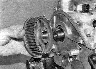
Figure 7.28,a. Install the camshaft sprocket...
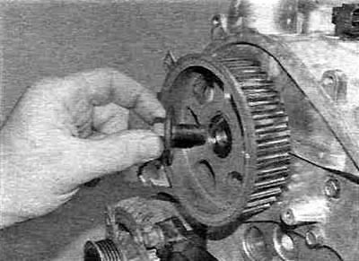
Figure 7.28,b....and secure it with the central bolt.
29. Before installing the tensioner, the following must be done: press the tensioner rod with a suitable tool until the holes on the rod and the tensioner body are aligned and insert a pin with a diameter of 1.3 mm into the aligned hole, then loosen the tightening of the tool and release the tensioner (see figure 7.29,a,b).
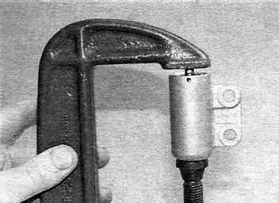
Figure 7.29,a. Using a clamp to compress the tensioner spring.
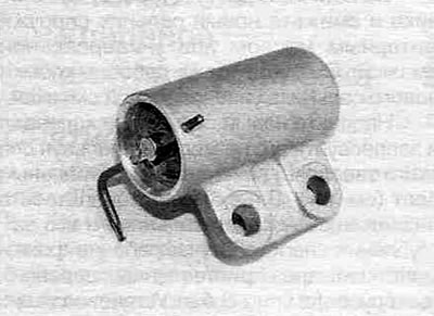
Figure 7.29,b. Using a hex key to secure the tensioner rod.
30. Where they were removed, install the tensioner roller and lever and tighten the mounting bolt, then install the tensioner on the cylinder block and tighten its mounting bolts to the specified torque (see Figure 7.30, a-c).
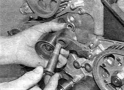
Figure 7.30,a. Install the tensioner roller and lever...
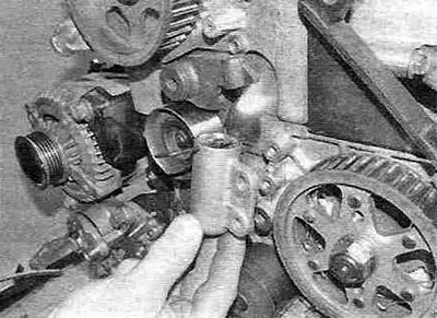
Figure 7.30, b....then install the tensioner...
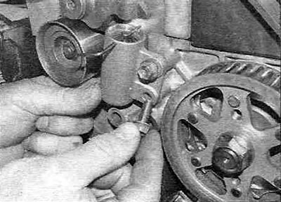
Figure 7.30, c....and tighten the mounting bolts.
31. Check the alignment of the TDC marks on the camshaft and crankshaft, then, in the order listed, put the timing belt on the camshaft drive sprockets, fuel injection pump, water pump and crankshaft, rear tension roller, oil pump sprocket and tensioner pulley (see Figure 7.31).
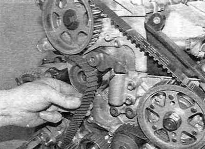
Figure 7.31. Installing the timing belt.
Warning. When installing the old timing belt, pay attention to the direction of rotation mark made when it was removed.
32. Check the position of the belt on the sprockets. Remove the pin securing the tensioner rod to release its spring and tighten the belt (see Figure 7.32).
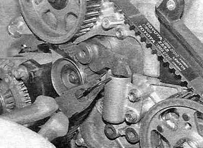
Figure 7.31. Installing the timing belt.
33. Temporarily tighten the crankshaft pulley mounting bolt, then turn the crankshaft two full turns and again set the piston of cylinder No. 1 to TDC of the compression stroke. Do not turn the crankshaft counterclockwise during this procedure. Check the alignment of the timing marks on the crankshaft and camshaft sprockets, then unscrew the crankshaft pulley mounting bolt.
34. Install the spacer sleeve - guide under the camshaft sprocket and tighten the bolt.
35. Install the right engine mount bracket onto the engine, then install the right engine mount onto the bracket (see paragraph 16) and tighten the mounting bolts to the specified torque (see Figure 7.35).
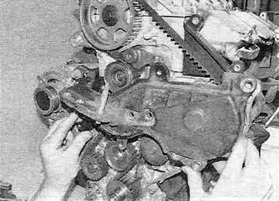
Figure 7.35. Install the right support bracket onto the engine.
Remove the hydraulic jack.
36. Install the support bracket in its place near the right headlight opening and tighten the mounting bolts.
37. Install the power steering pump together with the tensioner assembly and tighten the mounting bolts.
38. Install the guide/washer onto the crankshaft (see Figure 7.38).
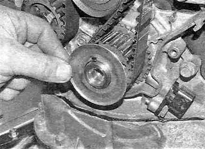
Figure 7.38. Install the timing belt washer/guide onto the camshaft.
39. Clean the mating surface of the lower timing cover and check the condition of the gasket. If replacement is necessary, remove the old gasket, then remove the paper backing and carefully press the new gasket into the groove around the perimeter of the cover. If there are gaps between the ends of the gasket, apply sealant to the problem areas.
40. Install the oil pump insulator (if there is one), then install the lower timing cover and tighten the mounting bolts (see Figure 7.40).
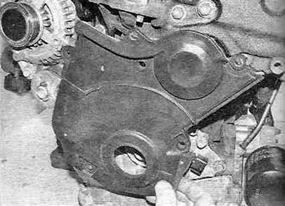
Figure 7.40. Installing the lower timing cover...
41. Clean the mating surface of the upper timing cover and check the condition of the gasket. If necessary, replace the gasket as described in paragraph. 39.
42. Install the upper timing belt cover and tighten the mounting bolts (see Figure 7.42).
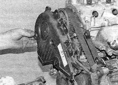
Figure 7.42. ...and the upper timing belt cover.
43. Install the crankshaft pulley (see Fig. 7.43].
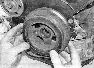
Figure 7.43. Installing the crankshaft pulley.
44. Install the accessory drive belt(s) as described in chapter 1B. If it was removed, install the right headlight (see chapter 12).
45. Install the glow plugs as described in Chapter 5.
46. Install the intercooler (see chapter 4B) and top engine covers.