



Note: Before beginning this procedure, prepare two M6 bolts with a 1 mm pitch and a length of 16-20 mm. These will be referred to as service bolts from here on.
Removal
1. Remove the valve cover as described in paragraph 4.
2. Remove the distributor (see chapter 5), if there is one.
3. Remove the timing belt, camshaft sprocket and rear timing cover (see paragraphs 7 and 9).
4. Measure the axial clearance of the camshaft with a dial indicator (see Figure 10.4).
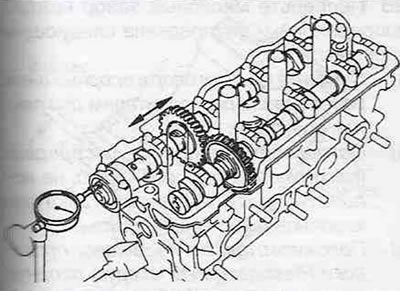
Figure 10.4. Install a dial indicator as shown in the figure and measure the camshaft end clearance.
If the clearance exceeds the specifications, replace the camshaft and/or cylinder head.
Exhaust camshaft
5. Check inlet the camshaft so that its locating pin is positioned at an angle of 10-45° to the vertical (see Figure 10.5).
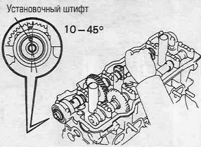
Figure 10.5. Rotate the intake camshaft so that its locating pin is at an angle of 10-45° to the vertical.
In this case, the cams of the exhaust camshaft will take such a position that the pressure of the valve springs will be evenly distributed along the entire length of the exhaust camshaft.
6. Fasten the main and auxiliary gears of the split driven gear of the exhaust camshaft together by screwing the service bolt into the threaded hole (see Figure 10.6).
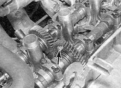
Figure 10.6. Screw the service bolt through the hole in the auxiliary gear into the threaded hole in the main camshaft gear (shown by the arrow).
7. Unscrew the bolts securing the outer cover (from the checkpoint) exhaust camshaft supports and remove the cover.
8. Gradually, 1/4 turn at a time, loosen the bolts on the 1st, 2nd and 4th exhaust camshaft bearing caps until they can be loosened by hand. Remove the covers of the 1st, 2nd and 4th supports.
9. Lastly, also gradually, 1/4 turn at a time, loosen the bolts securing the cover of the 3rd support, then unscrew the bolts by hand and remove the cover.
Warning. When unscrewing the cover bolts, make sure that the camshaft is lifted under the action of the valve springs evenly, without distortions. If the camshaft warps or rotates on the cam when the caps are released, reinstall the caps, tighten the bolts, and repeat the procedure from the beginning, again setting the intake camshaft dowel pin at an angle of 10-45° to the vertical. Do not attempt to align the camshaft by levering or applying force.
10. Lift the camshaft straight up and remove it from the cylinder head.
11. To remove the gears, clamp the camshaft by the hexagon in a vice.
12. Insert the second service bolt into the hole (without threads) on the auxiliary gear of the camshaft. Insert a screwdriver between the service bolts and turn the auxiliary gear counterclockwise. Remove the first service bolt from the threaded hole.
13. Remove the snap ring securing the auxiliary gear.
14. Now you can remove the wave washer, auxiliary gear and main gear spring washer from the camshaft.
Intake camshaft
15. Check inlet camshaft so that its locating pin is at an angle of 80-115° relative to the vertical (see Figure 10.15).
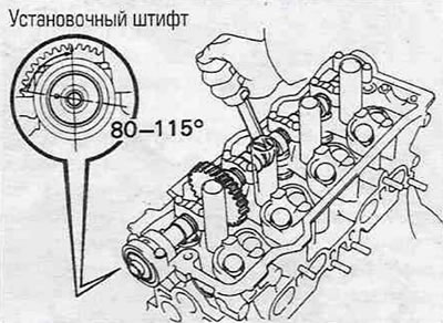
Figure 10.15. Turn the intake camshaft so that its locating pin is positioned at an angle of 80-115° to the vertical.
16. Unscrew the bolts securing the outer cover (from the timing belt) supports and remove the cover and seal.
Warning. If the cover does not come off freely, leave it in place without the bolts - do not use force to remove it.
17. Gradually, 1/4 turn at a time, loosen the bolts securing the covers of the 1st, 3rd and 4th supports until they can be unscrewed by hand. Remove the covers from the 1st, 3rd and 4th supports.
18. Lastly, gradually loosen the 2nd support cover mounting bolts by 1/4 turn until they can be turned by hand, then remove the cover. Warning. When unscrewing the cover bolts, make sure that the camshaft is lifted under the action of the valve springs evenly, without distortions. If the camshaft warps or rotates on the cam when the caps are released, reinstall the caps, tighten the bolts, and repeat the procedure from the beginning, re-aligning the dowel pin intake camshaft at an angle of 80-115° to the vertical. Don't try align the camshaft using a lever or by applying force.
19. Lifting the camshaft straight up, remove it from the cylinder head.
Examination
20. Measure the distance between the ends of the camshaft gear spring washer (see Figure 10.20) and compare it with the data given in the Specifications.
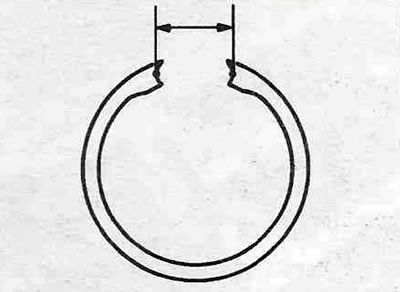
Figure 10.20. Measure the distance between the ends of the camshaft gear spring washer.
If not, replace the spring washer.
21. Mark carefully with a permanent marker, then remove the valve lifters and adjusting washers (see Figure 10.21).
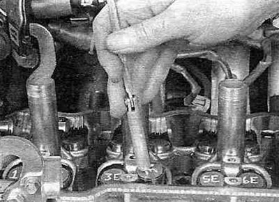
Figure 10.21. Wipe the oil off the adjusting washers and mark them; a magnet works well for removing the pushers.
22. Inspect the tappets for scratches and burrs (see Figure 10.22).
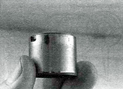
Figure 10.22. Wipe off the oil and inspect the condition of each tappet for signs of wear and scoring.
23. Measure the outside diameter of each push rod and the diameter of the corresponding pilot hole. By subtracting the result of the first measurement from the result of the second measurement, you will get the oil clearance value. Compare the obtained value with the Specification data. If the clearance value of at least one pair exceeds the permissible value, replace the cylinder head and/or valve lifters.
24. Place the tappets in a clean box, separate from each other, to avoid damage. Make sure that each tappet has the correct adjusting washer (don't mix them up).
25. Visually inspect the working surfaces of the camshaft cams and bearing journals for scuffing, chipping (cavities), metal abrasion and signs of overheating (areas of discoloration of flowers). Inspect each cam for damage (chipping, pitting) hardened surface.
26. Measure the height of each cam with a micrometer (see Figure 10.26).
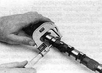
Figure 10.26. Use a micrometer to measure the height of each cam lobe on both camshafts.
Compare the measurement results with the Specifications. If the height of at least one of the cams is less than the permissible value, the camshaft must be replaced.
27. Measure the diameter of each bearing journal at several points using a micrometer (see Figure 10.27).
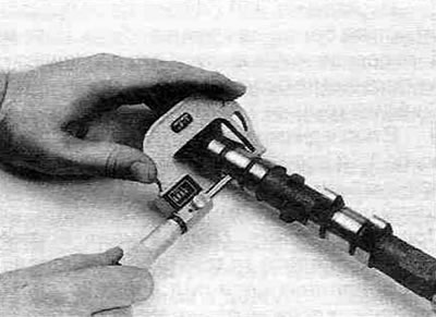
Figure 10.27. Use a micrometer to measure the diameter of each bearing journal on both camshafts.
Compare the measurement results with the Specifications. If the diameter of at least one of the journals is less than the permissible value, the camshaft must be replaced.
28. Check the oil clearance of each camshaft journal as follows:
- Clean the camshaft bearing caps and journals with lacquer thinner or acetone.
- Carefully install the camshaft (camshafts) into place without using any lubricant. The valve lifters must be removed.
- Place a piece of Plastigauge plastic wire on each support neck (see Figure 10.28,a).
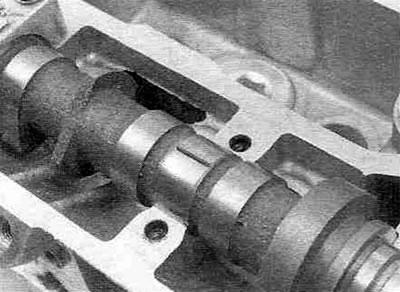
Figure 10.28,a. Place a piece of Plastigauge plastic wire on each camshaft journal.
- Install the support covers so that the arrows point towards the timing belt.
- Tighten the bolts to the specified torque in 1/4 turn increments.
Note: Do not rotate the camshaft during this procedure.
- Loosen the bolts and remove the support covers.
- Measure the width of the flattened section (at the widest point) according to the scale on the Plastigauge packaging (see Figure 10.28,b).
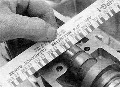
Figure 10.28, b. Measure the width of the flattened wire using the scale on the Plastigauge packaging and determine the oil gap size.
- If the gap in at least one journal/support pair exceeds the permissible value Specifications, replace the camshaft and/or cylinder head.
- Remove any wire fragments with your fingernail or the edge of a plastic credit card, as using any tool for this purpose can result in scratches and nicks on the working surfaces of the journals and supports, which is completely unacceptable.
29. Temporarily install the camshafts without the valve lifters and exhaust camshaft auxiliary gear.
30. Measure the engagement of the gear teeth with a dial indicator (the size of the gap between the gear teeth) (see Figure 10.30) and compare the measurement result with the data given in Specifications.
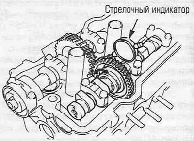
Figure 10.30. Install the dial indicator as shown in the figure and measure the gap between the gear teeth.
Installation
Intake camshaft
31. Lubricate the valve tappets with assembly gel and install them in their places, first making sure that all adjusting washers are present.
32. Lubricate the bearing journals and camshaft lobes with assembly gel.
33. Install the intake camshaft so that its locating pin is offset by 80° relative to the vertical (see Figure 10.15).
34. Apply a thin layer of anaerobic RTV sealant to the outer mating surfaces of the front support cover (see Figure 10.34).
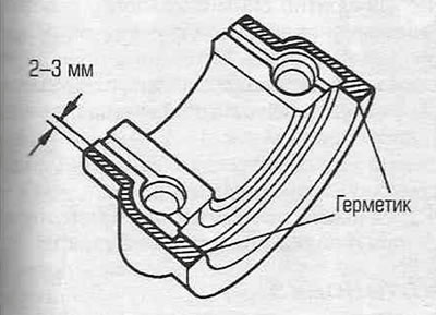
Figure 10.34. Apply sealant to the shaded areas of the front intake camshaft support cover.
Note: Install the lid immediately after applying the sealant, as it dries very quickly.
35. Install the camshaft bearing caps according to their numbering so that the arrows point towards the timing belt (see Figure 10.35).
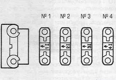
Figure 10.35. Installing the intake camshaft support covers - the arrows should point towards the timing belt.
36. In the recommended sequence (see Figure 10.36) tighten the support cap mounting bolts to the specified torque, making 1/4 turn at a time.
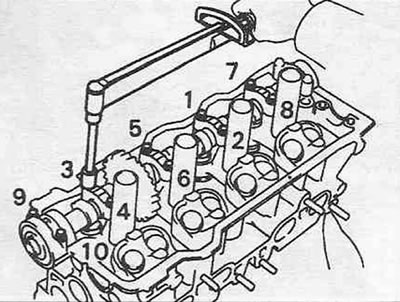
Figure 10.36. Sequence of tightening the intake camshaft support cover bolts.
37. After checking with paragraph 9, install a new camshaft oil seal.
Exhaust camshaft
38. Install the exhaust camshaft main gear. Install the spring washer, auxiliary gear and wave washer. Install the retaining ring.
39. Insert the service bolt into the unthreaded hole, turn the auxiliary gear with a screwdriver until it aligns with the threaded hole and screw the second service bolt into it. Tighten it to secure the main and auxiliary gears together and remove the first service bolt.
40. Lubricate the valve tappets with assembly gel and install them in their places, first making sure that all adjusting washers are present.
41. Lubricate the camshaft cams and bearing journals with assembly gel.
42. Check inlet camshaft so that its locating pin is at an angle of 10° to the vertical (see Figure 10.5).
43. Align the timing marks on the intake and exhaust camshaft gears (see Figure 10.43).
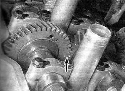
Fig. 10.43. Align the marks on the timing gears as shown.
Warning. In addition to the timing marks, the gears also have timing marks used during assembly (they are located above), - Be careful not to confuse them.
44. Lower the exhaust camshaft onto the supports in the cylinder head. Rotate the intake camshaft back and forth slightly until the exhaust camshaft is fully seated.
45. Install the support covers according to their numbering so that the arrows point towards the timing belt (see Figure 10.45).
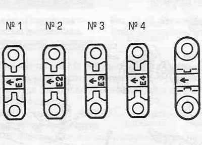
Figure 10.45. Installing the exhaust camshaft support covers - the arrows should point towards the timing belt.
46. Following the recommended sequence (see Figure 10.46), tighten the support cap mounting bolts to the specified torque, making 1/4 turn at a time.
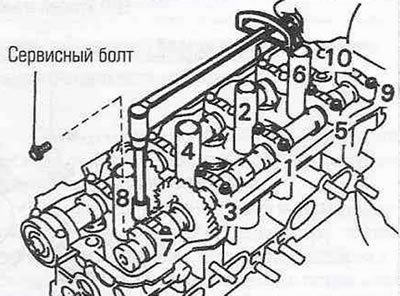
Figure 10.46. Sequence of tightening the exhaust camshaft support cover bolts.
47. Remove the remaining service bolt from the hole in the split gear.
48. Remove the semicircular plugs, replace the seals in them and install them back into the cylinder head. Install the rear timing cover and timing belt sprocket onto the intake camshaft. Tighten the sprocket mounting bolt to the specified torque, holding the camshaft from turning with an open-end wrench on the Allen key (see Fig. 7.13).
49. Install the timing belt (see paragraph 7).
50. The installation procedure for the remaining components is performed in the reverse order of the removal procedure.