



Removal
1. Remove the cylinder head cover, distributor, timing belt, camshaft sprocket and the upper section of the rear timing belt cover.
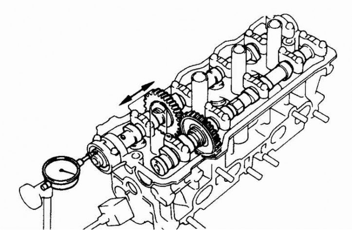
2. Measure the axial clearance of the shaft using a special device. If the clearance exceeds the permissible norm, replace the shaft and/or cylinder head. Secure the measuring device as shown in the figure.
Exhaust camshaft
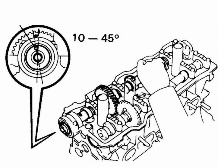
1. Rotate the intake valve shaft so that the pin at the base of the shaft is turned 10–45° to the left of the vertical position. The exhaust valve shaft cams will now be positioned so that the pressure of the valve springs will help remove the shaft with less effort.
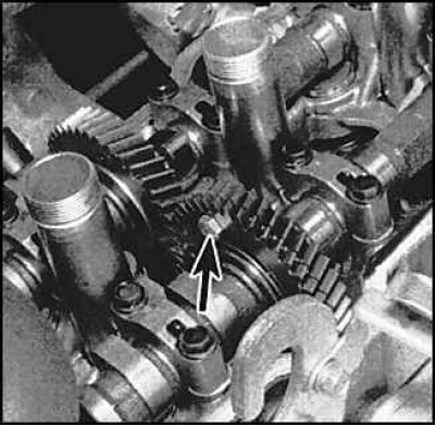
2. Secure the exhaust shaft auxiliary gear by inserting the bolt (arrow) into its hole and into the hole of the main gear.
3. Remove the exhaust valve shaft rear bearing cover bolts and remove the cover.
4. Loosen the bolts of the covers N1, N₂ and N4 one by one. Unscrew the bolts and remove the covers.
5. Loosen the cover bolts N3, unscrew the bolts and remove the cover.
6. Remove the shaft.
Intake camshaft
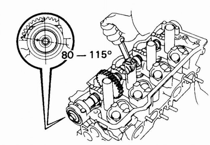
1. Rotate the intake valve shaft so that the pin located at the base of the shaft is turned 80–115° to the left of the vertical position.
2. Unscrew the bolts of the front shaft bearing cover, remove the cover and the seal.
3. Loosen the bolts of the covers N1, N3 and N4 one by one. Unscrew the bolts and remove the covers.
4. Loosen the bolts of cover N₂, unscrew the bolts and remove the cover.
Examination
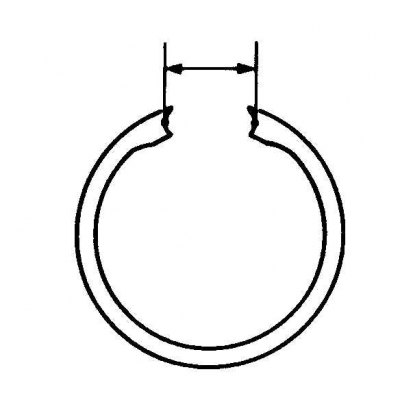
1. Measure the end clearance of the camshaft gear spring. Compare the result with the technical requirements.
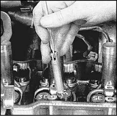
2. Wipe oil off gaskets, number and remove valve lifters and gaskets. Use a magnet to remove.
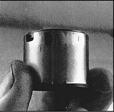
3. Inspect the lifters for wear and scratches.
4. Measure the diameters of the lifters and the inside diameters of their corresponding sockets. Subtract the lifter diameter from the socket diameter to obtain the lubrication gap. Compare the clearances with the specifications. If the clearances exceed the permissible norm, the head and/or lifters must be replaced.
5. Place the lifters in a separate box, do not mix up the lifter gaskets.
6. Inspect the camshaft cams and bearing journals for wear or damage.
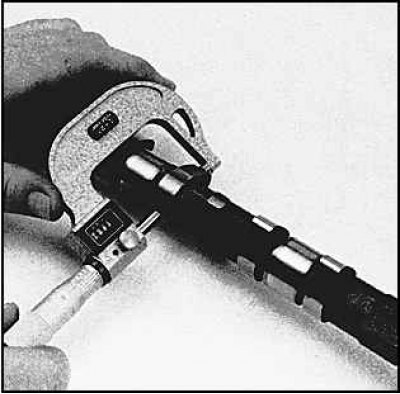
7. Using a micrometer, measure the height of each cam. Compare the values obtained with the technical specifications, replace the shaft if necessary.
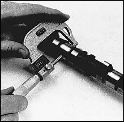
8. Using a micrometer, measure the diameters of the bearing journals. Compare the obtained values with the technical specifications, replace the shaft if necessary.
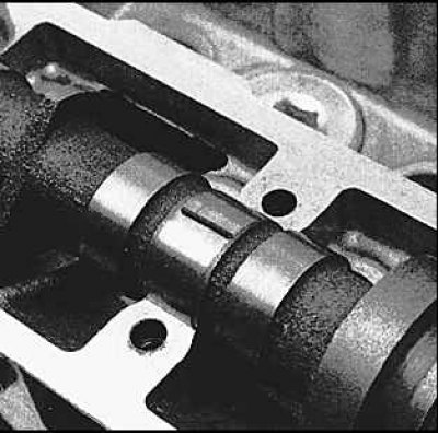
9. Place a plastic measuring strip on the bearing journal.
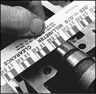
10. To determine the size of the lubrication gap, measure the width of the crushed strip of plastic using a special scale. If necessary, replace the camshaft and / or cylinder head.
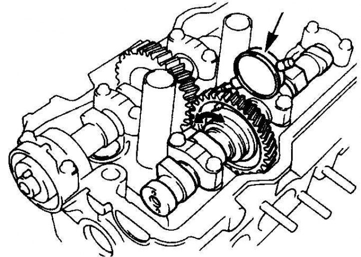
11. Measure the clearance between the teeth of the shaft gears using a special tool. Install the measuring device as shown in the figure. Compare the obtained value with the technical specifications.
Installation
Intake camshaft
1. Lubricate the cams and bearing journals of the shaft with molybdenum grease, lubricate the lifters and install them in their places.
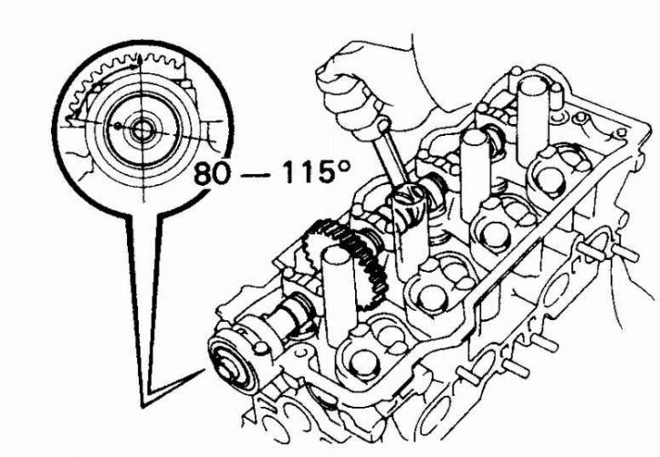
2. Install the shaft into the cylinder head. The pin at the base of the shaft should be turned 80° to the left of the vertical position.
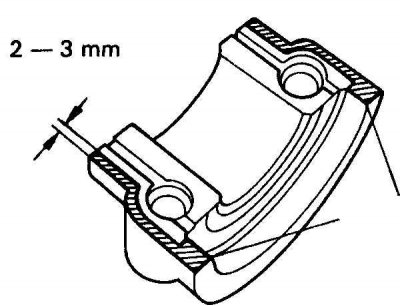
3. Apply sealant to the outer edge of the mating surface of the first bearing cap (marked with hatching).
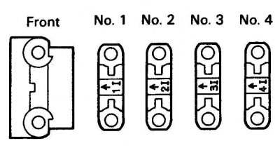
4. Install the bearing caps in the numbered order. The arrows on the caps should point towards the timing belt.
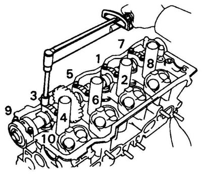
5. Tighten the cover bolts to the specified torque. Tighten the bolts in the sequence shown, one-quarter turn at a time.
6. Install a new seal.
Exhaust camshaft
1. Assemble the shaft gear.
2. Lubricate the cams and bearing journals of the shaft with molybdenum grease, lubricate the lifters and install them in their places.
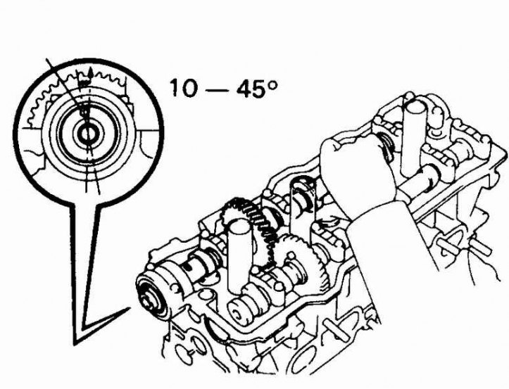
3. Rotate the intake valve shaft so that the pin at the base of the shaft is turned 10° to the left of the vertical position.
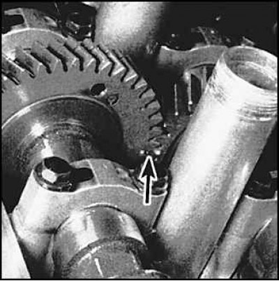
4. Align the shaft gears using the timing marks (arrow). Install the exhaust valve shaft. Rotate the intake valve shaft back and forth until the exhaust valve shaft is seated.
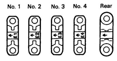
5. Install the bearing caps in the numbered order. The arrows on the caps should point towards the timing belt.
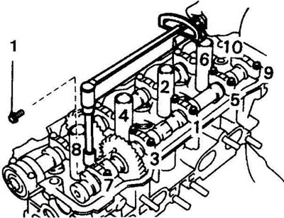
6. Tighten the cover bolts to the specified torque. Tighten the bolts in the sequence shown, one-quarter turn at a time.
7. Remove the bolt that locks the exhaust valve shaft gears.
8. Install the remaining parts.