



Note: Check and adjust the valve clearance on a cold engine.
1. (3SS-GE) Remove the intake chamber.
- a) Unscrew the four bolts and bracket No.2 of the intake chamber.
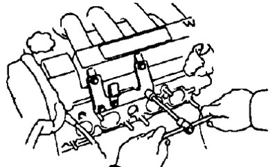
- b) Unscrew six bolts, two nuts, remove the intake chamber and gasket.
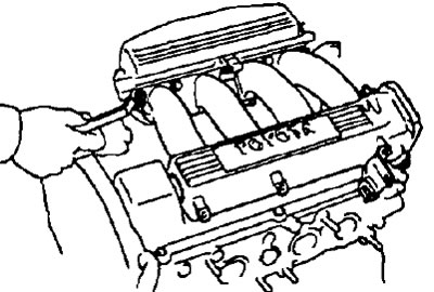
2. (3S-FE, 4S-FE) Remove the throttle cable bracket.
- a) Disconnect the control cable from the throttle linkage.
- b) Unscrew the two bolts and remove the accelerator cable mounting bracket.
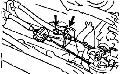
3. Remove the cylinder head cover.
(3S-FE, 4S-FE)
- a) Disconnect the four high-voltage wires from the clamp on the cylinder head cover.
- b) Disconnect the high-voltage wires by the rubber caps. Do not pull the high-voltage wires.
Note: Pulling or bending the wires may cause internal damage.
- c) Disconnect the two crankcase ventilation hoses from the intake manifold and cylinder head cover.
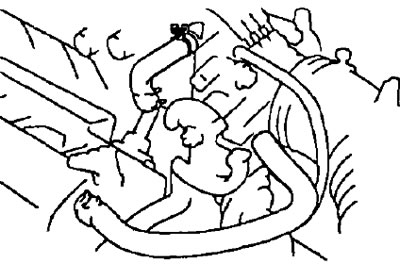
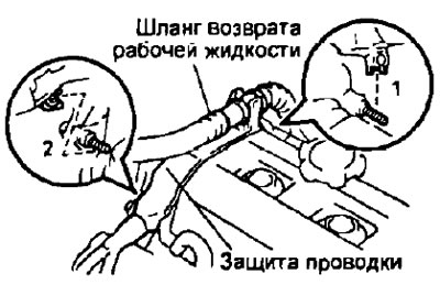
- d) Disconnect the power steering pump fluid return hose from the wiring harness protector.
- d) Remove the two wiring harness protection clamps from the timing belt cover No.2 mounting bolts in the sequence shown in the figure.
- e) Unscrew the four nuts, remove the spark plug tube seal, cylinder head cover and gasket.
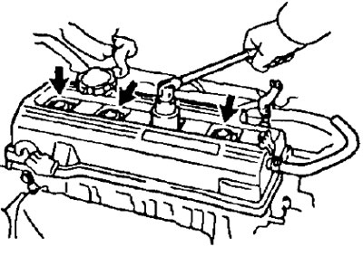
Note: For proper installation, arrange the spark plug tube seals in the order they were removed to minimize the possibility of oil leakage.
(3S-GE)
- a) Loosen the screws, remove the washers and cylinder head cover, gaskets.
3 Set the piston of cylinder No.1 to TDC of the compression stroke.
- a) Turn the crankshaft pulley and align its mark with the timing mark "0" on timing belt cover No.1.
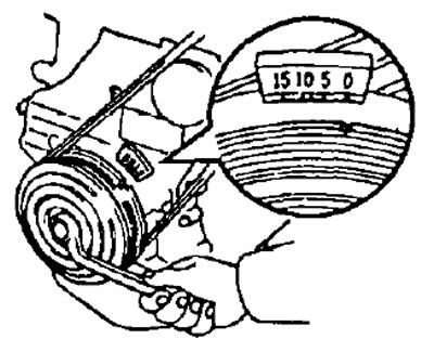
- b) Check that the valve tappets of cylinder No.1 are free and that the valve tappets of cylinder No.4 are clamped.
If not, rotate the crankshaft one revolution (360°) and align the mark as indicated above.
4. Check the valve clearance.
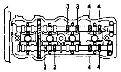
- a) Check the clearance in the valve drive indicated in the figure.
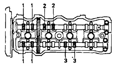
Using a feeler gauge, measure the clearance between the tappet and the camshaft.
Record the valve clearance measurements. They will be used later to determine the required shim size for replacement.
Valve clearance (cold engine):
- 3S-FE, 4S-FE:
- inlet - 0.19-0.29 mm
- outlets - 0.28-0.38 mm
- 3S-GE:
- inlet - 0.15-0.25 mm
- outlets - 0.20-0.30 mm
- b) Rotate the crankshaft one revolution (360°) and align the marks as indicated above.
- c) Measure the clearance in the valve drive indicated in the figure.
5. Adjust the valve clearance
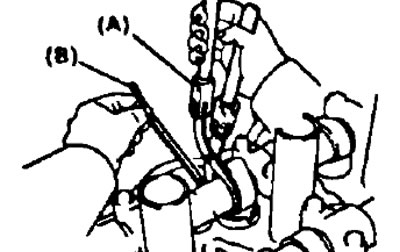
- a) Remove the adjusting washer. Turn the crankshaft so that the working protrusion of the camshaft cam is at the top.
- (3S-FE, 4S-FE) Position the pusher as shown in the figure.
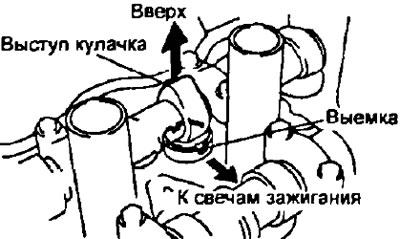
- Using the special tool (A), press the tappet and place the special tool (B) between the camshaft and the tappet.
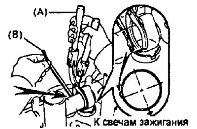
- Remove the special tool (A)
- Remove the adjusting washer using a small screwdriver and a magnetic rod.
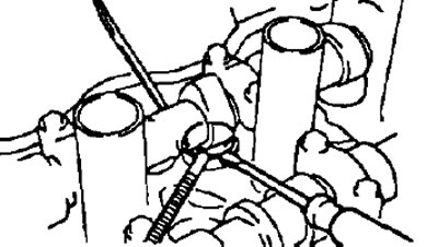
- b) Determine the size of the new adjusting washer using the following method:
- Using a micrometer, measure the thickness of the removed adjusting shim
- Calculate the thickness of the new adjusting shim so that the valve clearance is within the specified values.
- Thickness of the removed adjusting washer - T
- Measured valve clearance - A
- Thickness of new adjusting washer -N
- 3S-FE, 4S-FE:
- inlet - N = T + A (- 0.24 mm)
- outlet - N = T + A (- 0.33 mm)
- 3S-GE:
- inlet - N = T + A (- 0.20 mm)
- outlet - N = T + A (-0.25 mm)
- Select a new shim with a thickness as close to the calculated value as possible
Note:
- (3S-FE, 4S-FE) the adjusting washers have 17 sizes (thickness values) from 2.50 mm to 3.30 mm in 0.05 mm increments,
- (3S-GE) Adjusting washers have 27 sizes (thickness values) from 2.00 mm to 3.30 mm in 0.05 mm increments.
- c) Install a new adjusting washer into the tappet. Using the special tool (A), press the tappet and remove the special tool (B).
- d) Recheck the valve clearance
6. Install the cylinder head cover.
(3S-FE, 4S-FE)
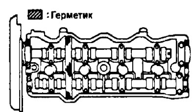
- a) Remove the old sealing material and apply sealant to the cylinder head as shown in the figure.
- b) Install the gasket on the cylinder head cover.
- c) Install the cylinder head cover and the four spark plug tube seals, tightening the nuts.
- Tightening torque - 23 Nm
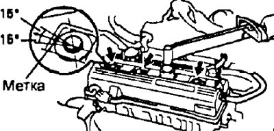
- d) Install the engine wiring harness guard by tightening the two timing belt cover #2 mounting bolts in the reverse order of removal.
- e) Install the power steering pump fluid return hose to the wiring harness guard.
- g) Connect the two crankcase ventilation hoses to the intake manifold and cylinder head cover.
- c) Install the high-voltage wires into the clamp on the cylinder head cover and connect them to the spark plugs.
(3S-GE)
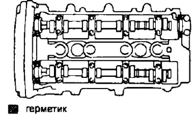
- a) Apply sealant to the cylinder head as shown in the figure.
- b) Install two gaskets on the cylinder head cover
- c) Install the cylinder head cover, washers and tighten the screws in several passes
7. (3S-FE, 4S-FE) Install the throttle cable bracket by tightening the two bolts and connect the control cables to the throttle linkage.
8. (3S-GE) Install the intake chamber.
- a) Temporarily tighten the intake plenum bracket No.2 bolts.
- b) Install the gasket and intake chamber, temporarily tighten the mounting bolts and nuts.
- c) Tighten the bolts and nuts.
- Tightening torque - 19 Nm