



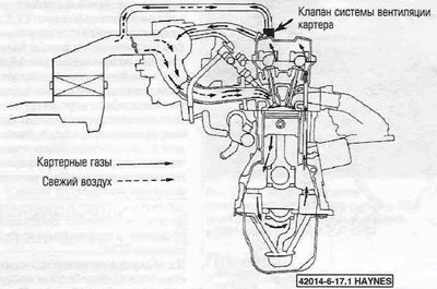
Figure 15.1. Diagram of the flow of crankcase gases in a typical forced crankcase ventilation system.
2. The main components of the system are the valve, the in-line filter-oil separator and the vacuum hoses connecting these components to the engine. The location of the positive crankcase ventilation valve can be seen in the figure 17.1,a,b.
3. To maintain stable idle speed, the valve throttles the flow of gases at high vacuum in the intake manifold. Under poor working conditions (for example, the piston rings are worn or broken) the system directs crankcase gases through the crankcase ventilation pipe to the air filter for subsequent afterburning in the cylinders.
4. Checking and replacing the crankcase ventilation valve is described in chapter 1A.
(The article is taken from a web resource toyotaman.ru)