



Oxygen sensor and air-fuel ratio sensor
General information
1. All models under consideration are equipped with the 0BD-II on-board diagnostics system for engine management systems, which provides the ability to monitor the accuracy of feedback signals between the oxygen sensors and the ECM. This is achieved by installing an oxygen sensor or air/fuel ratio sensor upstream of the catalytic converter and an oxygen sensor downstream of the catalytic converter. By receiving signals from these two sensors, which contain information about the composition of the exhaust gases at the inlet and outlet of the catalytic converter, the ECM can determine the efficiency of the converter and even accurately predict when it will fail.
2. The primary (inlet) oxygen sensor is installed in the exhaust manifold, and the secondary (outlet) oxygen sensor is located behind the catalytic converter. All models have heated oxygen sensor outputs (see Figure 11.2).
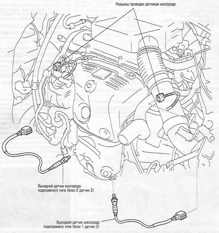
Figure 11.2. Location of the output oxygen sensors in models produced since 2001.
On some models, the inlet oxygen sensors are also of the heated type. On models produced since 2001, mixture composition sensors are installed at the inlet of the catalytic converter.
3. Do not confuse the oxygen sensor and the fuel-air mixture sensor. Despite their similar appearance, they have different operating principles and performance characteristics. Like the oxygen sensor, the air/fuel ratio sensor produces a voltage output signal to the ECM that changes in response to changes in the air/fuel ratio in the exhaust gas stream. However, unlike the oxygen sensor, it does not "switch" from one state to another relative to the stoichiometric (air/fuel ratio of the working mixture is 14.7:1) "threshold." Instead, it varies the voltage, controlled by the ECM, between 3.3 V at the positive terminal of the ECM fuel-air ratio sensor and 3.0 V at the negative terminal, directly proportional to the oxygen content in the exhaust gas. When the air-fuel mixture contained in the exhaust gases becomes leaner, the sensor output voltage increases (within its operating range of 3.0-3.3 V). Like the oxygen sensor, the air/fuel ratio sensor will not function properly if it is cold, so it (as in the oxygen sensor) a heating element is provided to speed up heating.
4. When servicing the sensor, special care must be taken:
- The flexible lead with connector has a permanent connection with the sensor that cannot be broken. Damage to the flexible lead or connector may affect the operation of the sensor.
- Dirt, grease, etc. must be removed from the connector and the outer end of the sensor.
- Do not use any solvents to clean the sensor.
- Do not drop or hit the sensor.
- To protect the sensor from external influences, a silicone case is placed on it. Make sure the cover fits correctly and is intact.
Removal
Note: Since the sensor is installed in the exhaust manifold or exhaust pipe, which contracts when it cools, it may be quite difficult to remove the sensor. In addition, there is a high risk of damaging the sensor (maybe it can still be used). Warm up the engine for a couple of minutes, then turn it off.
5. Disconnect the negative battery cable.
(The original text is posted on: www.toyotaman.ru)
6. If you are replacing the output sensor, raise the vehicle and support it on safety stands.
7. The input sensor can be replaced without lifting the vehicle (see Figure 11.7).
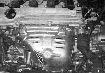
Figure 11.7. Location of the inlet oxygen sensor (shown by the arrow) block No. 2 contains models produced since 2001.
Disconnect the sensor wiring connector.
8. Unscrew the sensor from the exhaust manifold or exhaust pipe (see figure 11.8,a,b).
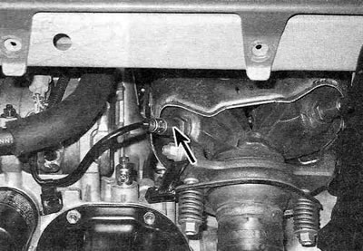
Figure 11.8,a. Location of the output oxygen sensor (shown by the arrow) block No. 1 contains models produced since 2001.
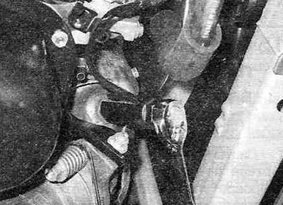
Figure 11.8, b. To unscrew the oxygen sensor from the exhaust manifold, use a special split head.
Note: It is easiest to unscrew the sensor using a special head with a slot, especially if you plan to replace the sensor. If you do not have such a head, be extremely careful when unscrewing the sensor.
Installation
9. Lubricate the threaded part of the sensor with a non-stick compound, which will make it easier to remove in the future. The new sensors already have grease on them; if you are going to install the old sensor back, the threaded part lubricant should be renewed. Install the sensor and tighten it securely.
10. Connect the sensor flexible lead connector to the main wiring harness.
12. Lower the car (if it was raised), take a test drive and make sure there are no fault codes generated.