



Exhaust gas recirculation (EGR) system (models produced before 2000)
General description
1. The EGR system is designed to reduce the amount of nitrogen oxides (NOX) in the exhaust gases by directing a controlled amount of exhaust gases through the system valve back into the intake manifold, diluting the working mixture, which reduces the temperature in the combustion chamber and leads to a decrease in exhaust toxicity.
2. The EGR system consists of a crankcase ventilation valve, a vacuum modulator, a vacuum switching valve, and vacuum hoses connecting these components to the throttle body. The degree of opening of the crankcase ventilation valve is determined by the vacuum, which is controlled by the ECM engine control module. The location of the components of the exhaust gas recirculation system (EGR) is shown in the figure 17.1,a.
Removal and installation
Crankcase ventilation valve
3. Remove the throttle body (see chapter 4A).
4. Disconnect the vacuum hose from the crankcase ventilation valve. Disconnect the EGR valve pipe, unscrew the mounting bolts and remove the crankcase ventilation valve from the intake manifold (see Figure 16.4).
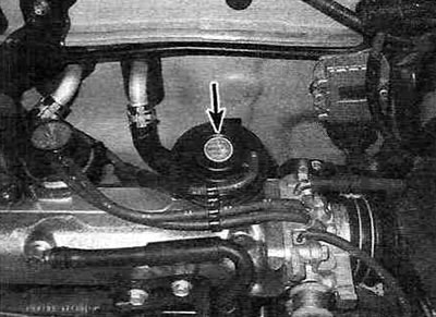
Figure 16.4. Location of the exhaust gas recirculation (EGR) valve (shown by the arrow).
Check the valve for sticking and carbon deposits. If the valve is sticking or clogged with deposits, it must be cleaned or replaced.
Warning. Do not immerse the valve in solvent.
5. Installation of the crankcase ventilation valve is carried out in the reverse order of its removal; don't forget to replace the gaskets, however.
Vacuum modulator of the EGR system and its filter
6. Carefully label and disconnect the vacuum hoses from the vacuum modulator. Remove the vacuum modulator from the bracket.
The publication is taken from the website ToyotaMan.ru
7. If you are going to install the old modulator back, remove the cover and check the filters (see Figure 16.7, a, b).
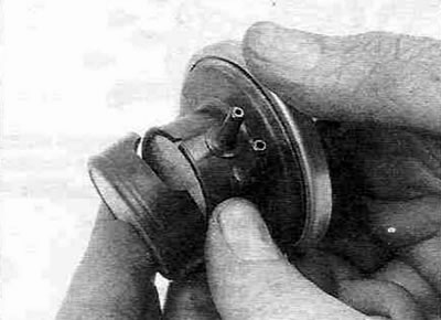
Figure 16.7,a. To remove the EGR system vacuum modulator filters, remove the cover...
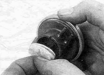
Figure 16.7, b.... remove the two filters and blow them out with compressed air; the outer filter should be placed with the rough side facing up.
Clean them with compressed air and replace the cover. If you cannot clean the filters, replace them or replace the entire modulator.
Vacuum Switching Valve (VSV)
8. Locate the vacuum valve near the exhaust manifold (see Figure 17.1,a). Disconnect the wiring connector from the valve. Carefully label and disconnect the vacuum hoses connected to the valve.
9. Remove the vacuum valve from the bracket. If you cannot remove the valve from the bracket, unscrew the bracket mounting bolt, remove it together with the valve from the car, and then separate the valve from the bracket.
10. Installation of the vacuum switching valve is carried out in the reverse order of its removal.