



Evaporative emission control system (EVAP)
General description
1. This system is designed to adsorb fuel vapors and, when the engine is running, to release them into the intake manifold (purge), where they mix with the working mixture. In models produced before 2000, the carbon canister is installed in the engine compartment (see Figure 17.1,a).
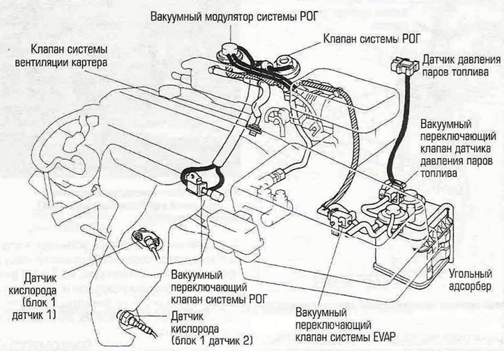
Figure 17.1,a. Location of EVAP system components (carbon fuel vapor adsorber) — models produced before 2000.
In models produced since 2001, the carbon canister is installed on the bottom of the car behind the fuel tank (see Figure 17.1,b).
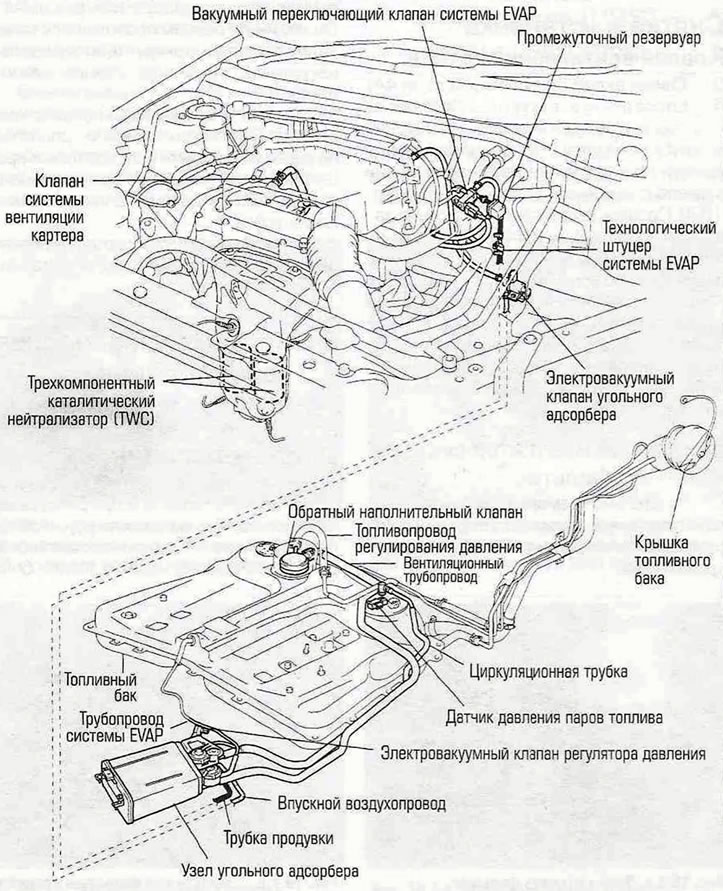
Figure 17.1,b. Location of EVAP system components - models produced since 2001.
2. When the engine is not running, fuel vapor passes through a system of hoses from the fuel tank, throttle body and intake manifold to the charcoal canister, where it is stored until the engine is started. When the engine is running, fuel vapors are removed from the canister by the purge control valve and sent to the intake manifold and then to the cylinders where they participate in the normal combustion process. The electronic purge valve is controlled directly by the ECM.
3. The fuel tank filler cap is equipped with a two-way valve for safety purposes. If the fuel vapor recovery system malfunctions, this valve releases fuel vapor into the atmosphere.
4. The EVAP system includes a fuel vapor pressure sensor. This sensor responds to excess fuel vapor pressure in the system. In models produced before 2000, it is installed on the engine shield. On 2001 and later models, the fuel vapor pressure sensor is mounted in the fuel pump/fuel gauge assembly on top of the fuel tank.
5. After the engine has run for some time and warmed up to the required temperature, the vacuum switching valve opens (purge control valve), allowing fuel vapor to escape from the canister into the intake manifold. Here, fuel vapors are mixed with air and then fed into the combustion chambers along with the working mixture.
6. The fuel tank vapor pressure sensor monitors changes in pressure inside the tank and, when the pressure exceeds a set threshold, opens the vacuum switching valve (see figure 17.6, a, b) and passes vapors from the fuel tank into the carbon adsorber.
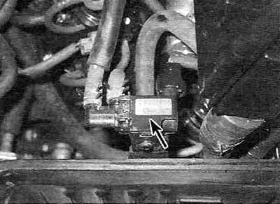
Figure 17.6,a. Electrovacuum valve of the EI/AP system (shown by the arrow) in models produced before 2000.
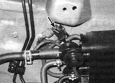
Figure 17.6,b. Location of the EUAP system solenoid valve (shown by the arrow) in models produced since 2001.
Removal and installation
Carbon adsorber
7. Disconnect the cable from the negative battery terminal.
8. If you are working on a 2001 or later model, raise the rear of the vehicle and install safety stands.
9. Disconnect the wiring connectors, carefully mark and disconnect the ventilation hoses from the charcoal canister, unscrew the mounting bolts and remove the charcoal canister from the vehicle. If necessary, refer to the illustrations at the beginning of this paragraph.
10. Installation of the carbon adsorber is carried out in the reverse order of its removal.