



Replacing CV joint boots
Note: If you need to replace your CV joint boots, consider all your options and estimate the time and cost before you begin. Make sure all necessary spare parts are available. You may find it more convenient to simply replace your drive shaft with a remanufactured one—some shops offer this service.
Note: Some manufacturers supply split covers as spare parts that do not require removal of the drive shaft for installation. This is very convenient, however, when replacing the cover, we recommend removing the shaft, cleaning the joint and replacing the grease, thereby extending the service life of the joint. Don't take it apart outer CV joint.
Disassembly
1. Remove the drive shaft (see paragraph 9).
2. Clamp the shaft in a vice, using wooden blocks to prevent damage. Check for excessive radial play, which indicates excessive wear of parts. Make sure there is no binding when the hinge moves. If the cover is damaged, it should be removed, the hinge washed, and its components checked; if the joint components are intact, it is filled with grease, a new cover is put on and the shaft is installed on the car.
3. Use a small screwdriver to bend back the clamp mounting brackets, then loosen the clamps and remove them from the drive shaft (see Figure 10.3).
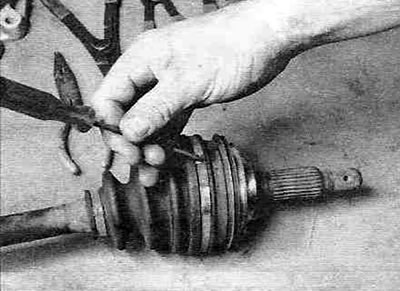
Figure 10.3. Using a small screwdriver, bend back the fixing edges to loosen the clamp.
4. Carefully pry the edge of the outer boot with a screwdriver and pull it off the CV joint. Old and worn boots can be cut off. Pull the inner CV joint boot off the housing and slide the housing off the tripod (see Figure 10.4).
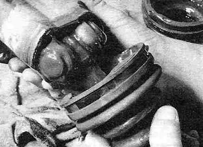
Figure 10.4. Pull the inner CV joint boot off the housing and slide the housing off the tripod.
5. Use a marker to mark the tripod and shaft to ensure proper alignment during installation.
6. Remove the tripod retaining ring with needle-nose pliers (see Figure 10.6).
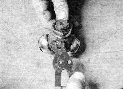
Figure 10.6. Remove the snap ring using needle-nose pliers.
7. Using a hammer and a copper spacer, knock the tripod off the shaft (see Figure 10.7).
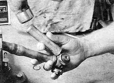
Figure 10.7. Using a hammer and a copper spacer, knock the tripod off the shaft.
8. If you haven't already cut them off, remove both boots from the shaft.
Note. Don't take it apart outer CV joint. If you're working on the right driveshaft, you'll also need to cut the dynamic damper clamp and remove the damper.
Note: The damper can be pressed using a hydraulic press. Before removing the damper, measure its position relative to the end of the shaft so that it can be installed in its original place during assembly.
Examination
9. Thoroughly wash all components with a suitable solvent until all grease is removed. Check the working surfaces of the tripod and frame for cracks, pitting, nicks, other defects, and signs of wear. It is not possible to check the condition of the working surfaces of the outer and inner races of the outer CV joint, but you can check the condition of the balls of the latter. If they have retained the correct shape, then the condition of the clips is acceptable. If the inner CV joint is worn out, you can buy this unit separately; if you need to replace the outer CV joint, you will have to buy both the drive shaft and the outer CV joint (they are sold assembled).
Assembly
10. To protect new covers from damage by the splines, wrap them with electrical tape. Place the clamps and boot(s) onto the shaft. Remove the electrical tape and place the tripod onto the shaft. Place the tripod on the shaft using a hammer through a copper spacer, aligning the marks made during its removal, and install the retaining ring. Apply grease to the tripod and inside the housing, insert the tripod into the housing and fill the volume of the housing around the tripod, squeezing out all the remaining grease from the repair kit tube into the hinge (see Figure 10.10, a-g).
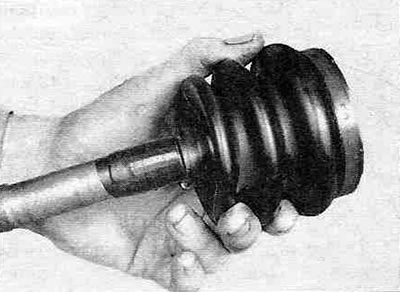
Figure 10.10,a. Wrap the splined portion of the drive shaft with adhesive tape to avoid damaging the CV joint boots.
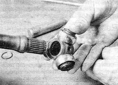
Figure 10.10,b. Install the tripod on the drive shaft so that the recess on the splined part of the tripod faces the shaft.
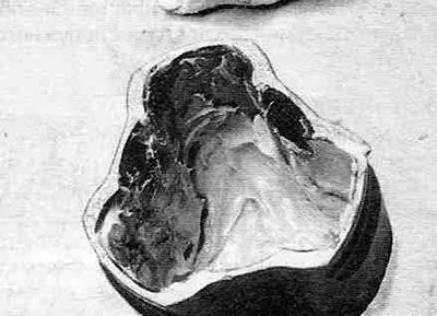
Figure 10.10, c. Apply a layer of grease to the bottom of the CV joint housing.
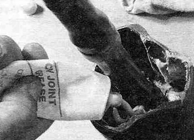
Figure 10.10, d. Place the boot clamps on the shaft and insert the tripod into the housing. Fill the volume of the housing around the tripod with grease.
11. Place the cover on the tripod body, aligning the cover cuff with the shaft groove. Adjust the drive shaft length to the specifications (see Figure 10.11).
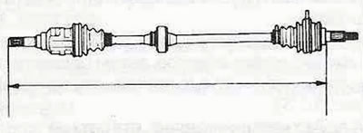
Figure 10.11. Before securing the Hinge Boot Clamps, the standard drive shaft length must be adjusted to the value prescribed in the Specifications.
12. Slide the tripod into the outer race so that it is positioned in the middle of the stroke. Use a screwdriver to carefully pry up the edge of the case to equalize the air pressure outside and inside it. Remove the screwdriver. Fasten the clamps to the covers (see Figure 10.12, a-g).
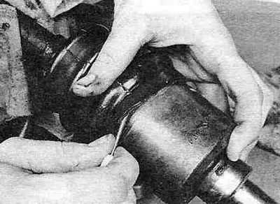
Figure 10.12,a. Carefully pry up the edge of the case with a small (not sharp) screwdriver to equalize the air pressure outside and inside it.
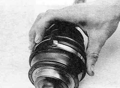
Figure 10.12, b. To secure the new clamp, bend its tongue down...
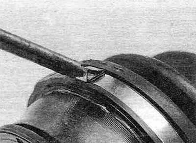
Figure 10.12, c....then fix it in place by bending the clamping tabs.
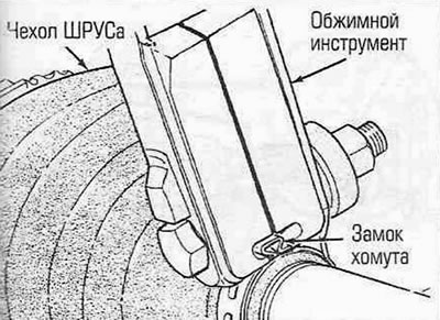
Figure 10.12, d. If the new cover kit includes a clamp that requires compression to be tightened, a special tool is required. Instead of a special tool you can (with a little skill, acting carefully) use nippers or pliers.
13. Install the drive shaft assembly (see paragraph 9).