



Front drive shaft
Removal
1. Remove the wheel trim or hub cap. Remove the cotter pin and unscrew the lock nut (models produced before 2000). On models produced since 2001, use a punch to pry the nut out.
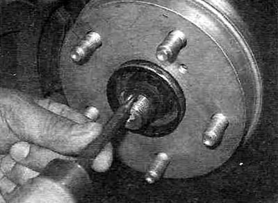
Figure 9.1. If the hub nut is locked, pry it loose using a punch and hammer (for clarity, the wheel has been removed).
2. "Strote" (loosen the tightening) hub nut using a socket head and a long, strong ratchet (see Figure 9.2).
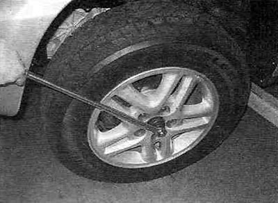
Figure 9.2. You can only loosen the drive shaft/hub mounting nut using a long, powerful wrench.
3. Loosen the wheel nuts, lift the car with a jack and place it on safety supports. Remove the wheel. Drain the transmission fluid (oil) (see chapter 1A or 1B).
4. Unscrew the nuts and bolts securing the ball joint to the lower suspension arm, then, pressing the arm down, separate it from the ball joint (see chapter 10). Now you can unscrew the drive shaft/hub mounting nut.
5. Using a gentle rocking motion, pry the steering knuckle/hub assembly outward and disengage the splined drive shaft from the hub.
Note: If the shank does not come out of the splined joint, tap it with a plastic hammer. Tie the outer end of the drive shaft with a piece of wire to avoid putting stress on the inner CV joint and damaging its boot.
6. If you are working with the right-hand drive shaft on a model without all-wheel drive (2WD) with automatic transmission, remove the bolts securing the intermediate bearing bracket (see Figure 9.6).
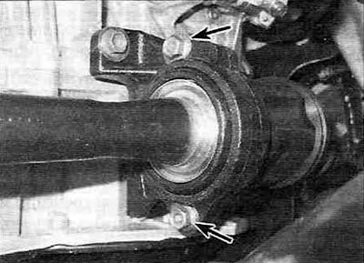
Figure 3.6. Loosen the intermediate support bearing bracket mounting bolts (shown by arrows).
If you are working on a non-4WD model with a manual transmission, remove the snap ring using a hammer and screwdriver.
7. Carefully release the inner joint of the drive shaft or, if the model is equipped with it, the intermediate shaft from engagement with the gearbox drive by pressing its housing with a large screwdriver or a mounting blade away from the gearbox housing or bearing support bracket (see Figure 9.7).
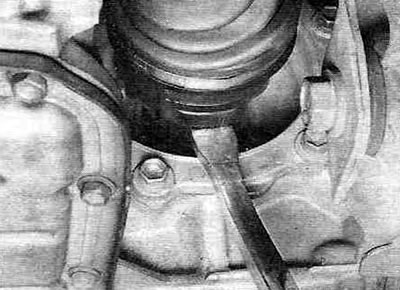
Figure 9.7. To separate the inner CV joint of the drive shaft from the gearbox, pry it off with a large screwdriver or a tire iron - you may need to give it a strong, sharp blow to the end of the lever with a brass hammer.
While supporting both CV joints, carefully remove the drive shaft from the vehicle.
Installation
8. Remove the old snap ring from the groove on the inner CV joint tailpiece and install a new one (see figure 9.8,a,b).
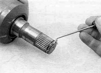
Figure 9.8,a. Remove the old snap ring from the groove on the inner end of the drive shaft using a small screwdriver or awl.
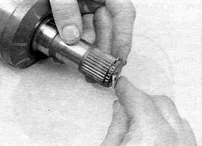
Figure 9.8,b. To install a new retaining ring, insert one end of it into the groove and gradually press it into it, circling it around the shaft until it is completely in the groove.
Lubricate the differential or intermediate shaft seal with multi-purpose grease and, holding the CV joints, install the drive shaft.
9. Insert the splined shank of the inner CV joint or intermediate shaft into the differential gear and make sure that the snap ring snaps into the groove of the gear. If you are installing the drive shaft/intermediate shaft assembly, tighten the intermediate bearing mounting bolts or install the snap ring (in accordance with the design).
10. Apply a thin coat of multi-purpose grease to the outer ball joint spline, push the strut/steering knuckle assembly outward and engage the ball joint splines into the hub.
11. Connect the ball joint to the lower control arm and tighten the fasteners to the torque specified in the Specifications chapter 10.
12. If you are working on a 2001 or later model, install a new driveshaft/hub nut. Tighten the hub nut securely, but do not attempt to tighten it to the specified torque until the vehicle is lowered to the ground.
13. Firmly grasp the inner CV joint housing (but not for the drive shaft), pull it outward to ensure that the drive shaft is securely seated in the gearbox.
14. Install the wheel and tighten the lug nuts, then lower the vehicle.
15. Tighten the wheel nuts to the torque specified in the Specifications section 1A or 1B. On models produced before 2000, install a new lock nut and secure it with a new cotter pin. On 2001 and later models, tap the nut collar into the drive shaft spline using a punch and hammer.
16. Fill the gearbox with transmission oil (fluid) of the prescribed type and volume (see chapter 1A or 1B).
Rear drive shaft — All-wheel drive (4WD)models
Removal
17. Remove the wheel trim or hub cap. Remove the cotter pin and unscrew the lock nut. "Strote" (loosen the tightening) hub nut using a socket head and a long, powerful ratchet.
18. Chock the front wheels to prevent the car from rolling. Loosen the wheel nuts, lift the car with a jack and place it on safety supports. Remove the wheel.
19. On models with anti-lock brake system (ABS), remove the ABS speed sensor (see chapter 9).
20. Remove the drive shaft/hub mounting nut together with the crown lock.
21. Apply relative position marks to the flanges of the drive shaft and differential (see Figure 9.21).
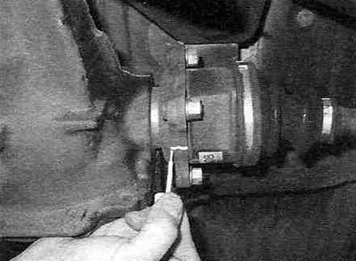
Figure 9.21. Mark the relative positions on the flanges of the drive shaft and the differential output shaft.
22. Unscrew the four nuts and remove their washers (see Figure 9.22), disconnect the drive shaft from the differential flange, then disconnect the outer CV joint tail from the hub.
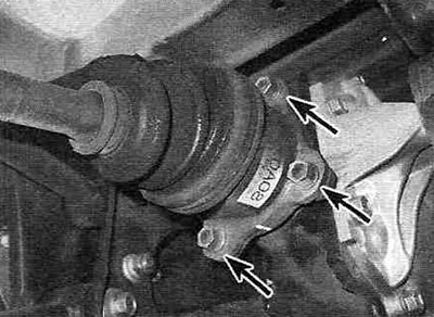
Figure 9.22. Unscrew the four nuts and washers (the fourth nut is not visible).
Installation
23. Installation of the rear drive shaft is carried out in the reverse order of its removal. Replace the drive shaft/hub nut. Tighten the hub nut securely, but do not attempt to tighten it to the specified torque until the vehicle is lowered to the ground. Install the wheel and tighten the lug nuts, then lower the vehicle. Tighten the wheel nuts to the torque specified in the Specifications section 1A or 1B. Tighten the drive shaft/hub retaining nut to specification, then install the crown lock and new cotter pin.