
Throttle body 4-cylinder engine
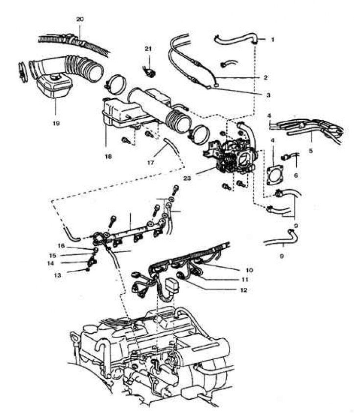
1. Crankcase ventilation spool; 2. Cable acceleration in low gear; 3. Damper cable; 4. Vacuum hose; 5. Tank hose with absorber; 6. Idle speed controller connector; 7. Gasket; 8. Cooling hose; 9, 21. Air hose; 10. Injector connector; 11. Knock sensor connector; 12. Connector for crankshaft rotation sensor; 13. Insulator; 14. Nozzle; 15. Ring; 16. Seal; 17. Vacuum hose; 18. Flow rate sensor connector; 19. Air intake hose; 20. Engine harness; 23. Damper body
V6 engine throttle body
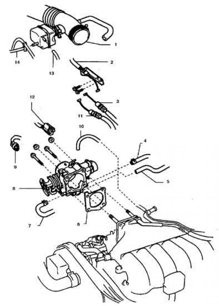
1. Air intake hose; 2. Cruise control cable; 3. Damper cable; 4, 7. Coolant hose; 5, 13. Air hose; 6. Gasket 8. Damper body; 9. Idle speed controller connector; 10. Vacuum hose; 11. Cable acceleration in low gear; 12. Gate sensor connector; 14. Power steering pump hose
Examination
Valve Body Vacuum Hose
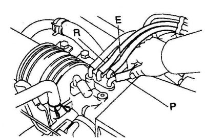
Table of modes and test results
| Designation of the union of a vacuum hose | At idle | At 3500 rpm |
| P | There is a vacuum | There is a vacuum |
| E | No vacuum | There is a vacuum |
| R | No vacuum | There is a vacuum |
Valve Body Vacuum Hose (a / m 1997-98)
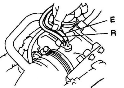
Table of modes and test results (for vehicles 1997-98)
| Designation of the union of a vacuum hose | At idle | At 3500 rpm |
| E | No vacuum | There is a vacuum |
| R | No vacuum | There is a vacuum |
1. Check for smooth throttle linkage.
2. Start the engine, disconnect the vacuum hose, check the vacuum with a vacuum gauge and compare with the table data.
Replacement
1. Disconnect the battery from the ground.
2. Remove the air duct by loosening the clamps.
3. Disconnect the cable from the damper, remove the cable bracket and set aside.
4. If the vehicle is equipped with an automatic transmission, then disconnect the transmission throttle cable, remove the bracket and set aside.
5. Label and disconnect all vacuum hoses from the throttle body.
6. Disconnect the connector from the housing and unscrew the bolts.
7. Remove the throttle body and gasket. Clean the case, blow all channels with compressed air. Do not wipe the damper sensor with solvent.
Installation
1. Installation is carried out in the reverse order.
2. Tighten the mounting bolts to the specified torque.