



Attention! The crankshaft can only be removed after the engine has been removed from the vehicle. Remove the flywheel first (or leading disk), tensioner pulley, belt (chain), sump, oil receiver, oil pump, front cover and connecting rods with pistons.
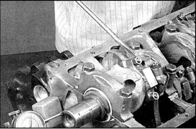
1. Preliminarily check the crankshaft axial play. Move the crankshaft toward the rear of the engine, applying maximum force, and in this position set the indicator scale to zero. Then push the crankshaft toward the front of the engine and read the indicator readings. The amount of axial play is equal to the distance the shaft has moved.
2. If the axial clearance exceeds the standard value, check the wear of the thrust surfaces of the crankshaft cheeks. If their wear is insignificant, then the half rings should be replaced
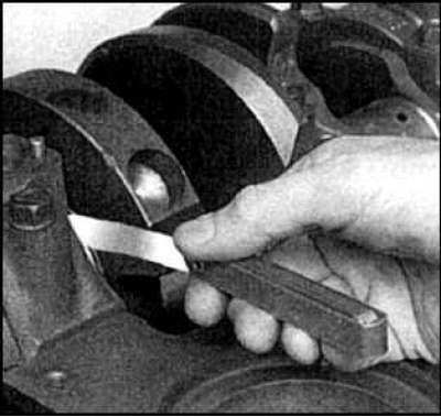
3. If you don't have a dial indicator, you can measure the clearance using a set of feeler gauges. Carefully move the crankshaft toward the front of the engine and measure the axial clearance by placing the feeler gauges between the crankshaft web and the surface of the 3rd (thrust) main bearing on 4-cylinder engines, or the 2nd main bearing (V6).
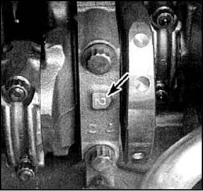
4. Check the covers for orientation arrows and cylinder number markings (indicated by an arrow). Typically, covers are numbered starting from the front of the engine, with orientation arrows pointing toward the front.
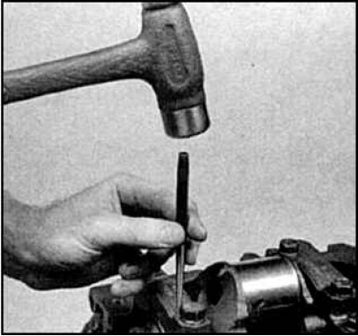
5. If there is no marking, apply marks with a stamp. Marks are applied to the boss next to the bolt head.
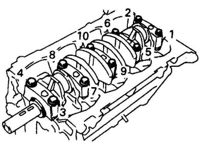 | 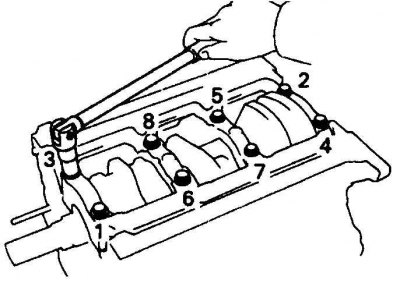 |
6. Loosen the cap bolts 1/4 turn at a time in the reverse order (left - 4-cylinder engines, right - 6V engines) until the bolts can be turned by hand. On 3VZ-FE (V6) engines, the caps are made as a single frame. Mark the position of the studs, which are used as guide pins.
7. Carefully move the covers and remove them together with the insert.