



Contents: Removal and installation ↓ Adjustment ↓
Removal and installation
1. The brake light switch is located on the bracket at the top of the brake pedal (Fig. 12.1).
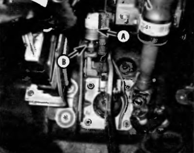
Fig. 12.1. The table signal switch (A) is located at the top of the brake pedal. Loosen the lock nut (B) and then unscrew the switch from the corresponding bracket
2. Disconnect the electrical connector from the switch.
3. Loosen the lock nut and unscrew the switch from the pedal bracket.
4. Installation is performed in the reverse order of removal.
Adjustment
5. Check and, if necessary, adjust the brake pedal height (see chapter 1).
6. Loosen the switch lock nut and adjust the switch position so that the distance the plunger protrudes is within the range specified in Specifications at the beginning of this chapter (Fig. 12.6). (If you are unable to measure this distance, adjust the plunger so that it lightly contacts the pedal stop.) Tighten the lock nut.
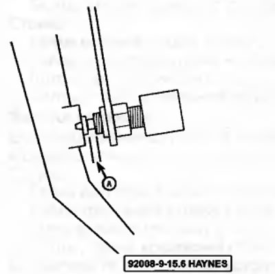
Fig. 12.6. To adjust the position of the brake light switch, loosen the lock nut and turn the switch until the plunger stroke (dimension A) corresponds to the value specified in Specifications at the beginning of this chapter, and then tighten the lock nut
7. Connect the switch electrical connector. Make sure that the brake lights come on when you press the brake pedal and go out when you release the pedal. If not, repeat the adjustment procedure until the brake lights work properly.
8. Check and, if necessary, adjust the free travel of the brake pedal (see paragraph 13).