
Elements
Actuator assembly
2. The actuator assembly is installed in the engine distance and consists of an electro-hydraulic pump and solenoid valves (pic. 2.2).
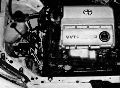
Pic. 2.2. ABS actuator (installed in the right front of the engine compartment or below the brake booster, depending on the model)
- A) The electric pump creates hydraulic pressure for filling the tanks in the actuator, which supplies pressure to the brake system. The pump and tanks are located in the actuator.
- b) Solenoid valves modulate the pressure in the brake line during ABS operation.
Speed sensors
3. These sensors are located on each wheel, and when the sensor wheels rotate, they generate small electrical impulses and send a signal corresponding to the wheel speed to the electronic control unit.
4. The front speed sensors are mounted on the front steering knuckles close to the sensor impulse wheels, which, in turn, are connected to the outer CV joints of the front axle shafts.
5. The rear wheel sensors are bolted to the rear hub supports. Impulse sensor wheels integrated with rear hubs
ABS control unit
6. The ABS control unit is installed together with the actuator and is the brain of the ABS system. The control unit must receive and process information received from wheel speed sensors in order to control the pressure in the hydraulic line to prevent wheel lockup. In addition, the control unit constantly monitors the system, even during normal driving, in order to detect malfunctions that occur in the system.
Diagnostics and repair
7. If the warning light on the front panel turns on and stays on when the vehicle is moving, the ABS system requires attention. Although special electronic testers are needed to correctly diagnose the ABS system, you can perform a few pre-welds yourself before contacting your dealer's service department.
- A) Check the brake fluid level in the reservoir.
- b) Check up reliability of docking of electric sockets of the block of electronic control.
- V) Check the electrical connectors in the hydraulic control box.
- G) Check fuses.
- d) Trace the wiring harness to each wheel and make sure all connections are tight and the wiring is intact.
8. If the above preliminary checks do not solve the problem, you should contact the dealer's technical service department or another specialized service station for diagnostics of the car. Due to the complexity of this system, all actual repairs must be performed by a qualified auto mechanic.
Attention. Do not attempt to repair the ABS wiring harness. The ABS system is sensitive to even the smallest changes in resistance. Repairing the wiring harness can cause the resistance values to change and cause the system to malfunction. If the ABS wiring harness is damaged, it must be replaced.
Warning. Switch off the ignition before disconnecting or making any electrical connections.
Wheel speed sensor - removal and installation
9. Loosen the wheel nuts. Raise the vehicle and place secure stands under it. Remove the wheel.
Attention! If the vehicle is equipped with electronically controlled air suspension, turn off the suspension height control switch before raising the vehicle.
10. Turn the ignition key to the off position (OFF).
11. Trace the electrical wiring coming from the sensor. Mark its wiring and disconnect all brackets and clips. Then disconnect the electrical connector.
12. For front wheel speed sensors on all models and rear wheel speed sensors on all wheel drive models, remove the bolt and carefully remove the sensor from the steering knuckle/hub support (pic. 2.12, a). The rear wheel speed sensor on 2WD models is built into the rear hub support and cannot be removed without removing the hub support (pic. 2.12, b). The procedure for removing the rear hub is described in chapter 10.
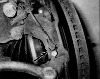
Pic. 2.12, a. Front wheel speed sensor (rear wheel speed sensor on all wheel drive models is similar)
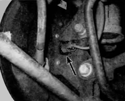
Pic. 2.12, b. Rear wheel speed sensor electrical connector on two wheel drive models (the sensor itself is inserted into the rear hub support)
13. Installation is carried out in the reverse order of removal Tighten the fastening element securely.
14. Install the wheel. Install wheel nuts and tighten securely. Lower the vehicle and tighten the wheel nuts to the specified torque given in the Specifications at the beginning of this chapter.