
Health check
1. Depress the brake pedal several times with the engine off and check that there is no change in pedal travel.
2. Depress a pedal and start the engine. If the pedal drops slightly, the vacuum booster is working properly.
Leak test
3. Start the engine and turn it off after one or two minutes. Slowly depress the brake pedal several times. If the pedal drops less each time, the booster is sealed.
4. Depress the brake pedal while the engine is running, and then stop the engine with the pedal depressed. If no change in pedal travel is observed after holding the pedal for 30 seconds, the booster is sealed.
Removing
Note. On 2003 and prior Highlander models with ABS and traction control (traction control) removal and installation of the brake booster requires the use of special tools and procedures. The ABS and traction control actuator must be removed and then bled during installation (under pressure), using special tools. It is recommended to entrust the removal and installation of the vacuum brake booster to the specialists of the dealership or other specialized service station.
5. Do not disassemble the vacuum brake booster. This requires special tools that are usually not available at non-specialized service stations or auto parts stores. The vacuum booster is quite complex in design and due to the fact that it has a significant effect on the efficiency of the brakes, it should not be repaired, but replaced with a new or rebuilt one.
6. On 2004 and later Lexus models, remove the air box deflector from the engine compartment (see chapter 11).
7. Remove the air filter housing (see chapter 4).
8. Remove the brake master cylinder (see paragraph 6). To provide space for removal of the booster, on some models it may be necessary to completely remove the brake lines that run in front of the master cylinder, and not just disconnect them from the master cylinder. Other brake lines that run before the brake booster can be separated from the bulkhead and carefully moved to the side.
9. Carefully disconnect the vacuum hose from the brake booster.
10. In the car, remove the knee buffer and the tie behind it.
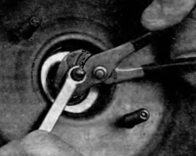
11. Remove the brake pedal return spring near the top edge of the pedal. Use pliers to remove the pin clamp and then remove the pin (pic. 9.11).
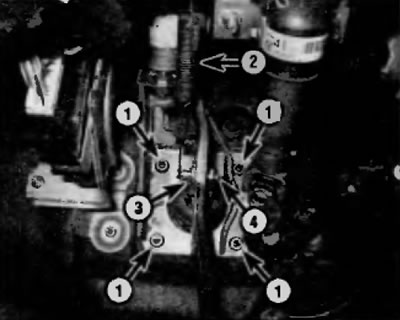
Pic. 9.11. Installing a vacuum brake booster
1 nuts
2 Return spring
3 pin clamp
4 Pin
12. Turn away four nuts of fastening of the vacuum amplifier of brakes on a partition. Then move the amplifier away from the baffle until the studs are completely out of the mating holes (pic. 9.11).
Installation
13. Installation is carried out in the reverse order of removal. Tighten the booster mounting nuts to the specified torque as specified in Specifications at the beginning of this chapter.
14. If a new brake booster is installed, check the gap between the brake booster rod and the master cylinder piston (pic. 9.14, a-d), proceeding as follows:
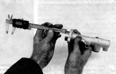
- A) Measure how far the rod protrudes from the front of the brake booster relative to the mating surface of the master cylinder, including the gasket (in the presence of) (pic. 9.14, a). Record the result. This is size A
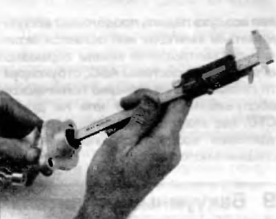
- b) Measure the distance from the master cylinder support flange to its end (pic. 9.14, b). Record the result. This is size B.
- V) Measure the distance from the end of the eye cylinder to the bottom of the recess in the piston (pic. 9.14, a). Record the result. This is size S.
- G) Subtract dimension B from dimension C. and then subtract dimension A from the difference between B and C. This is the gap between the piston rod and the piston.
- d) Compare the gap you calculated with the value given in the Specifications at the beginning of this chapter. If necessary, adjust the stem length to ensure correct clearance (pic. 9.10, g).
Pic. 9.14, a. Measure how far the rod protrudes from the front of the brake booster relative to the mating surface of the master cylinder, including the gasket
Pic. 9.14 b. Measure the distance from the master cylinder support flange to its end
Pic. 9.14, c. Measure the distance from the end face of the master cylinder to the bottom of the notch in the piston
Pic. 9.14, d. To adjust the length of the amplifier rod, grasp the knurled part of the rod with pliers and screw or unscrew the adjusting sheet, achieving the desired setting
15. After the final installation of the master cylinder and brake hoses and pipelines, the height and free play of the brake pedal should be adjusted and air should be bled from the system. Refer to the relevant sections of this chapter for a description of these procedures.