
Attention! Models covered in this manual are equipped with an assisted restraint system (SPS), better known as «airbag system». To prevent accidental deployment of airbags, which could result in injury, be sure to deactivate the airbag system before working near components of the airbag system (see paragraph 25).
Examination
Application. Before proceeding with the diagnosis of electrical circuits, check the fuses.
1. Disunite an electric socket of a sound signal.
2. To test the horn, use a jumper wire to apply battery voltage to the horn terminal. If the horn does not sound, replace it.
3. If the horn works, check for voltage at the terminal while the horn button is pressed. If there is voltage at the terminal, check the horn ground circuit.
4. If there is no voltage to the horn, check the relay (see paragraph 5).
5. If the relay is in good condition, check that its electrical circuits are not energized - the power circuit and the control circuit. If either circuit is not receiving voltage, inspect the wiring between the relay and the flat fuse panel.
6. If both relay circuits are energized, press the horn button and test the electrical circuit from the relay to the horn button for continuity with respect to «masses». If there is no continuity, check the electrical circuit for an open. If no open circuit is found, replace the horn button.
7. If the integrity of the electrical circuit is not «mass» through the horn button, check for an open or short circuit in the electrical circuit from the relay to the horn.
Replacement
Note. There are two beeps. One is located in front of the A/C condenser and the other is in front of the engine compartment fuse and relay box below it.
8. Disconnect the electrical connector (pic. 18.8, a, b).
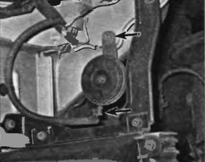
Pic. 18.8, a. To shine the horn located in front of the fuse and relay box below it, disconnect the electrical connector and remove the support bracket bolt
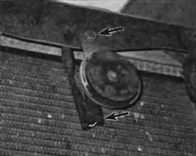
Pic. 18.8, b. To remove the sound signal, which is located in front of the air conditioner condenser, disconnect the electrical connector and remove the support bracket bolt
9. Turn out a bolt from an arm.
10. Installation is carried out in the reverse order of removal.