
Company Honda Company Ford Company Skoda Company Kia Company Mazda Company Mercedes Company Renault
English Русский
Български
Беларускі
Український
Српски
Hrvatski
Română
Polski
Slovenský
Magyar
Bookmark Articles Sitemap Contacts
ToyotaMan.ru


Camry Corolla Corona Carina Land Cruiser Highlander 4Runner RAV4 Others
RAV 4 XA20 (2000-2005) RAV 4 XA10 (1994-2000)

Replacing the oxygen (O2S) and air-fuel ratio (A/F) sensors [Toyota RAV4 XA10]

  • Main
  • RAV4
  • XA10 (1994-2000)
  • Power unit
  • Toxicity reduction system
  • Replacing the oxygen (O2S) and air-fuel ratio (A/F) sensors
0
Vehicles are equipped with an OBD-II on-board diagnostic system in the engine management system, which provides feedback between the oxygen sensor and the engine control module (PCM). This is achieved by installing a primary oxygen sensor or air-fuel ratio sensor before the catalytic converter and a secondary oxygen sensor after the converter. Depending on the oxygen content in the exhaust gases, the oxygen sensor induces a voltage of a corresponding magnitude. Based on this data, the engine control unit changes the opening time of the injectors and the ratio of fuel in the air-fuel mixture. In order for the complete combustion of the combustible mixture to occur and for the exhaust gases to be free of harmful substances, there must be 1 part fuel per 14.7 parts air.

By determining the composition of the exhaust gases before and after the catalytic converter, the PCM determines the efficiency of the catalytic converter.
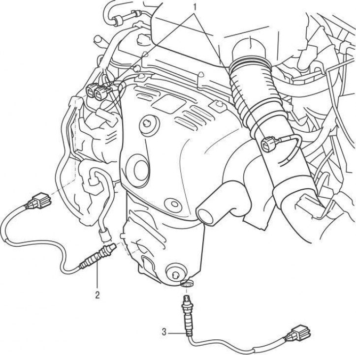


Figure 7.16. Location of oxygen sensors on models since 2001: 1 – electrical connectors; 2 – oxygen sensor (block 2, sensor 2); 3 – oxygen sensor (block 1, sensor 2)


Primary (in the direction of movement of exhaust gases) the oxygen sensor is located in the exhaust manifold or in the tailpipe, and the secondary one is located behind the catalytic converter (figure 7.16).


Caution! Do not confuse the oxygen and air-fuel mixture sensors. They are similar in appearance, but they work differently and have different performance characteristics.


Like the oxygen sensor, the air fuel ratio sensor converts information into an output voltage that is transmitted to the engine control unit. The signal magnitude is proportional to the air/fuel mixture ratio in the exhaust gas flow. The air-fuel ratio sensor changes the output voltage from 3.3 to 3.0 V depending on the proportion of oxygen in the exhaust gas stream. Like the oxygen sensor, the air-fuel ratio sensor only begins to function properly after warming up, for which purpose heaters are installed on the sensors.

When servicing sensors take the following precautions:

The oxygen and air-fuel ratio sensors have a permanently connected braid with wires and an electrical connector that are not separable from the sensor. Damage to the wiring harness or removal of the wiring harness or electrical connector may impair the functionality of the sensors.

Prevent dirt, grease and other substances from coming into contact with the sensors.

Do not use solvents to clean sensors.

Do not throw or hit the sensors.

Since the sensors are mounted in the exhaust manifold or tailpipe, they are prone to burn-in, making them very difficult to remove on a cold engine.

Replacement of oxygen sensors (O2S) produce as follows:

To eliminate the possibility of damaging the sensors, run the engine for 1–2 minutes, then turn it off. Removing the sensors is now easier, but care must be taken to avoid burning yourself on the hot exhaust manifold and tailpipe.


Turn off the ignition and disconnect the ground wire from the battery.

If it is necessary to remove the secondary sensor, raise the vehicle on a lift.
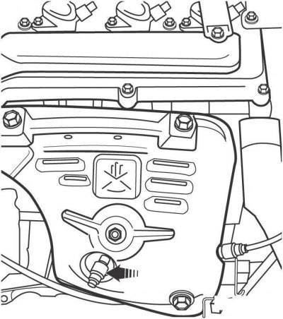


Figure 7.17. Location of the primary oxygen sensor on bank 2 on models since 2001


The primary sensor can be replaced without raising the vehicle (figure 7.17).

Disconnect the electrical connector located on the oxygen sensor wires.
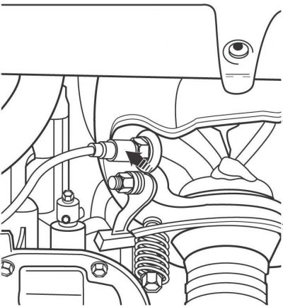


Figure 7.18. Location of the secondary oxygen sensor on bank 1 on models since 2001


Remove the sensor from the exhaust manifold or tailpipe (figure 7.18). Use a socket wrench to remove the sensor.

Apply a non-stick compound to the sensor threads to make it easier to remove the sensor later. The threads of the new sensor are already coated with a non-stick compound. Screw in the sensor and tighten it securely.


Connect the sensor electrical connector.

Lower the car.

Install the sensor in the reverse order of removal.
This article is available at: russian, bulgarian, belarusian, ukrainian, serbian, croatian, romanian, polish, slovak, hungarian
The article material has been checked: Kolokoltsev Grigory
Share information:
◀ Previous
RAV 4 XA10: Toxicity reduction system
Next ▶

Replacing the camshaft position (CMP) sensor on 1998 and later models
Replacing the crankshaft angle sensor (CKP)
Replacing the coolant temperature (ECT) sensor
Replacing the engine air temperature (IAT) sensor on pre-2001 models
Replacing the Mass Air Flow (MAF) sensor on 2001 and later models
Replacing knock sensors
Replacing the vehicle speed sensor (VSS)
Replacing the Idle Air Control (IAC) Valve
Positive Crankcase Ventilation (PCV) system
Exhaust gas recirculation (EGR) system on 2001 and later models
Similar articles on other Toyota models

➥ Replacing the fuel filter Toyota Camry XV20 (1996-2001)
➥ Replacing fuel injectors (1CD-FTV) Toyota Corolla Verso 3 (2004-2009)
➥ Lean Air-Fuel Ratio Sensor (4A-FE Engine with Lean Burn… Toyota Corona T190 (1992-1997)
➥ Replacing the fuel filter Toyota Carina T190 (1992-1996)
➥ Replacing the fuel filter Toyota Cruiser 60/80 (1980-1997, petrol)
➥ Oxygen sensors — replacement Toyota Highlander 1 (2000-2007, petrol)
Link in different formats to this article
Comments and feedback from visitors
No comments yet


Add two numbers 16 + 42


RAV 4 XA20 (2000-2005) 
  • General information
  • Introduction to manual
  • User manual
  • Daily care
  • Maintenance (petrol)
  • Maintenance (diesel)
  • Troubleshooting
  • Power unit
  • Gasoline engines (before 2000)
  • Petrol engines (since 2001)
  • Diesel engines
  • Engine overhaul
  • Cooling and heating
  • Fuel system (petrol)
  • Fuel system (diesel)
  • Engine electrical equipment
  • Control system (petrol)
  • Control system (diesel)
  • Transmission
  • Manual gearbox
  • Automatic gearbox
  • Clutch and drive shafts
  • Chassis, running gear
  • Brake system
  • Front suspension
  • Rear suspension
  • Steering system
  • Body and interior
  • Exterior (external elements)
  • Interior (internal elements)
  • Doors, locks and windows
  • Electrical equipment
  • Equipment and devices
  • Electrical circuits
RAV 4 XA10 (1994-2000) 
  • General information
  • User manual
  • Maintenance
  • Power unit
  • Petrol engine 3S-FE
  • Petrol engine 1AZ-FE
  • Engine overhaul
  • Cooling and air conditioning
  • Fuel and exhaust system
  • Ignition system
  • Toxicity reduction system
  • Transmission
  • Clutch
  • Mechanical gearbox
  • Automatic gearbox
  • Cardan and drive shafts
  • Chassis, running gear
  • Brake system
  • Car suspension
  • Steering
  • Body and interior
  • Exterior (external elements)
  • Interior (internal elements)
  • Doors, locks and windows
  • Electrical equipment
  • Equipment and devices
  • Power devices
  • Electrical circuits
ToyotaMan.ru © 2018–2026 • Mobile version • Interesting about Toyota • Administration • Sitemap: EN BG BY UA RS HR RO PL SK HU • Search system • Bookmark
Camry Vista-V40 • Camry XV10 • Camry XV20 • Camry XV30 • Corolla Verso-AR10 • Corolla E80 • Corona T190 • Carina T170 • Carina T190 • Land Cruiser J70 (diesel) • Land Cruiser J60 (petrol) • Land Cruiser J100 • Highlander XU20 (petrol) • 4Runner N120 • RAV4 XA10 • RAV4 XA20 • Duet M100 • Dyna Y50 •
We require cookies to enable some interactive features. Is that ok with you?