
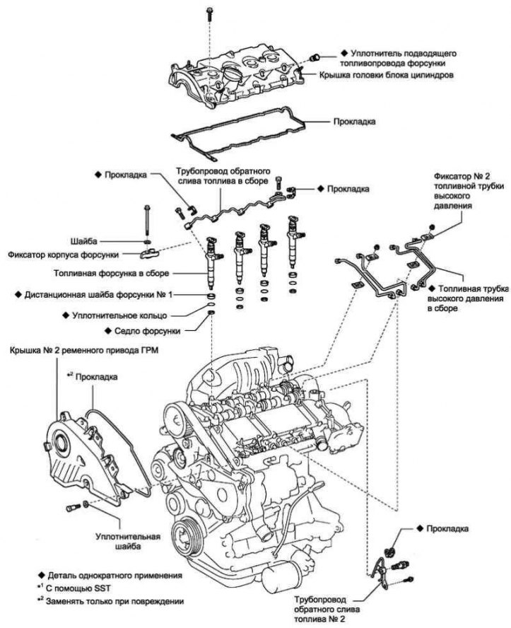
Pic. 2.524. Engine fuel supply components (1CD-FTV)
Note. If a malfunction occurs and the engine ECU registers an incorrect injector correction code, the engine may start to jerk or idle unevenly. It can also cause engine malfunction and shorten engine life.
Note. To optimize fuel injection performance, the engine ECU adjusts the injection timing for each cylinder. The engine ECU stores and uses the injector correction values, which are indicated as a 30-character alphanumeric code on the top of the injector.
Note. When replacing an injector, the correction code for the new injector is entered into the engine ECU. When replacing the engine ECU, the correction codes for all injectors must be entered into the new ECU.
Note. After replacing the engine ECU, DTC P1601 will be output when the ignition is turned on. The injector correction codes must be registered in the engine ECU. To clear the DTC, first set the correction codes, then turn off the ignition and wait at least 30 seconds.
Disconnect the negative battery terminal.
Removing the vacuum receiver assembly
Disconnect 2 vacuum hoses and connector.
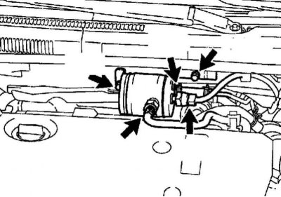
Pic. 2.525. Vacuum tank mount
Turn out 2 bolts and remove a vacuum receiver (pic. 2.525).
Remove the windshield wiper arm cover.
Remove the left windshield wiper arm with brush assembly.
Remove the right windshield wiper arm with brush assembly.
Remove the upper edge seal of the engine compartment bulkhead.
Remove the top right air vent fairing.
Remove the top left air vent fairing.
Remove the wiper motor with linkage assembly.
Remove the top outer hood panel.
Remove the hole cover in the radiator shroud.
Remove the #1 engine top cover.
Remove the air filter with air duct assembly.
Remove the battery.
Remove the lower left engine shield.
Remove air duct #1.
Removing the high pressure fuel pipes
Remove the 2 nuts and disconnect the 2 upper retainers for the high pressure fuel pipes from the intake manifold.
Using SST, disconnect the high pressure fuel pipe from the common rail fuel line.
Using SST, disconnect the high pressure fuel pipe from the injector.
After removing the high pressure fuel pipe, cover the common rail fuel line with vinyl tape and cover the injector inlet with vinyl tape or a plastic bag to prevent dirt and foreign particles from entering.
Remove the high pressure fuel lines.
Remove the #2 timing belt cover.
Using a screwdriver, remove the 4 injector O-rings from the cylinder head.
Removing the cylinder head cover
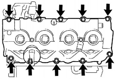
Pic. 2.526. Fastening of a cover of a head of the block of cylinders
Turn out 10 bolts, remove a cover of a head of the block of cylinders and a lining (pic. 2.526).
Removing the fuel return pipe assembly
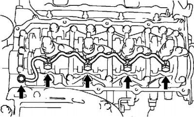
Pic. 2.527. Fastening of the pipeline of the return drain of fuel assy
Unscrew the hollow connecting bolt and 4 hollow bolts, then remove the fuel return pipe and 5 gaskets (pic. 2.527).
Note. When removing, place a rag under the fuel return pipe so that the fuel remaining in the pipe does not spill onto the cylinder head.
Turn out 4 bolts, remove 4 washers and 4 clamps of the nozzle body.
Remove the fuel injector assembly.
Note. Each injector has its own fuel injection characteristics. When removing the nozzles, they should be arranged in order to be installed in their original places during assembly.
Remove 4 injectors from the cylinder head.
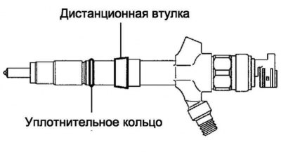
Pic. 2.528. Fuel injector O-rings and spacers
Remove o-rings and spacers from injectors (pic. 2.528).
Remove the 4 injector seats from the cylinder head.
Register injector correction codes (in case of replacement of injectors with new ones).
Installing complete injectors
Install 4 injector seats in the cylinder head.
Install the spacers and o-rings on the injectors.
Lubricate the injector O-rings with engine oil.
Install the injectors into the cylinder head.
Note. Insert the nozzles into the nozzle sockets.
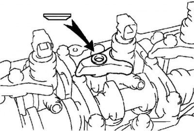
Pic. 2.529. Retainer installation
Establish clamps of cases of atomizers, as it is shown in drawing 2.529.
Hand-tighten the camshaft bearing cap bolt to secure the injector body retainer.
Note. Make sure the washers are installed in the correct position.
Note. When tightening the fixing bolt of the injector body retainer, make sure that the parts are located correctly.
Note. Lubricate the threads of the injector housing retainer bolts with engine oil.
Install No. 1, No. 2, No. 3, and No. 4 high-pressure fuel pipes to the injectors, then finger-tighten the fastening nuts.
Install 5 new gaskets and #1 fuel return line. Hand-tighten the 4 hollow bolts.
Tighten the 4 injector housing fixing bolts.
Tightening torque: 26 Nm.
Remove 4 high pressure fuel pipes.
Installing the fuel return pipe assembly
Install the fuel return line and 5 new gaskets.
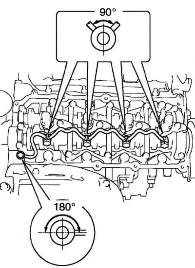
Pic. 2.530. Scheme of installation of the fuel return pipeline assembly
Note. Make sure the gaskets are installed in the correct position. Gaskets are installed so that the protrusion is located within the limits shown in Figure 2.530.
Lubricate the 4 hollow bolts and the hollow connecting bolt fitting with engine oil.
Hand-tighten the 4 hollow bolts and the hollow connecting bolt fitting.
Tighten the 4 hollow bolts and the hollow connecting bolt to the prescribed torque.
Tightening torque: 18 Nm - hollow bolts, 22 Nm - hollow connecting bolt fitting.
Check for fuel leakage at the fuel return pipe connection.
Disconnect the fuel line, then remove the bolt, check the valve, No. 2 fuel return line and gasket.
Using SST, install the bolt, install the No. 2 fuel return line and gasket to the cylinder head.
Tightening torque: 8.8 Nm - bolt, 21 Nm - SST.
To check the tightness, lubricate with soapy water (or other suitable liquid) the place of connection of the fuel return pipeline No. 2.
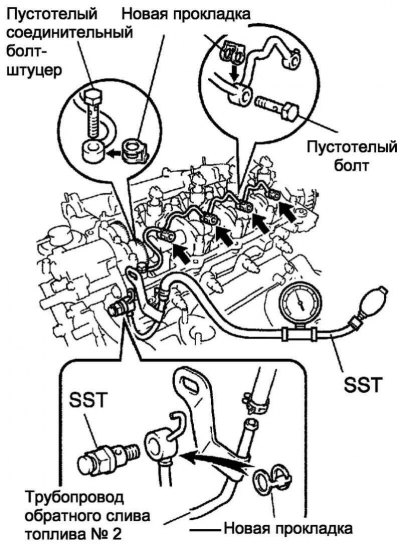
Pic. 2.531. Pipeline Test Diagram
Use SST (turbocharger pressure gauge). Connect the SST to the injector at the #2 fuel return line connection. Then apply a pressure of 100 kPa for 60 seconds to ensure that there are no air bubbles at the piping connection (pic. 2.531).
After checking the tightness, wipe off the soap solution from the pipeline connection.
Remove the 2 SSTs, then remove the bolt, remove the #2 fuel return line and gasket.
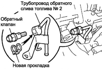
Pic. 2.532. Fitted piping parts
Install a new gasket and reinstall the No. 2 fuel return line with check valve and secure the parts with the bolt (pic. 2.532).
Tightening torque: 8.8 Nm - bolt, 21 Nm - check valve.
Attention! Never disassemble the check valve on the engine.
Connect the fuel line to the #2 fuel return line.
Installing the cylinder head cover
Remove old sealant (FIPG).
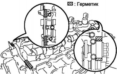
Pic. 2.533. Sealant application scheme
Apply sealant to the cylinder head (pic. 2.533).
Install the gasket on the cylinder head cover.
Install the cylinder head cover and secure with 10 bolts.
Tightening torque: 13 Nm.
Install 4 new fuel line seals.
Install timing belt cover #2.
Install the high pressure fuel lines.
Note. When replacing injectors, the high pressure fuel lines must also be replaced.
Note. The tubes should be installed on an engine that has cooled to room temperature or below.
Install the 2 lower high pressure fuel pipe clamps to the intake manifold.
Remove the plastic bag from the injector and the vinyl tape from the common rail fuel line.
Loosely install the new high pressure fuel pipe.
Using SST, tighten the nut securing the high pressure fuel pipe to the common rail fuel line.
Tightening torque: 31 Nm with SST, 34 Nm without SST.
Note. Use a torque wrench with a lever length of 30 cm.
Note. After installing the high pressure fuel pipes, make sure they are not deformed and installed correctly. If the tubes are deformed or cannot be installed correctly, replace them with new ones.
Using SST, tighten the nuts securing the high pressure fuel lines to the injectors.
Tightening torque for old tubing: 42 Nm with SST, 46 Nm without SST; for new tubing: 31 Nm with SST, 34 Nm without SST.
Install 2 upper high pressure fuel pipe clamps to the intake manifold.
Tightening torque: 5.0 Nm.
Install duct #1.
Install the battery.
Install the air filter with air duct assembly.
Install the #1 engine top cover.
Install the upper outer hood panel.
Install the wiper motor with linkage assembly.
Install the right windshield wiper arm with brush assembly.
Install the left windshield wiper arm with brush assembly.
Install the vacuum reservoir and secure with 2 bolts.
Tightening torque: 8.3 Nm.
Attach 2 vacuum hoses and connector.
Connect the negative terminal to the battery terminal.
Tightening torque: 5.4 Nm.
Check for fuel leaks.
Note. In active diagnostic mode, fuel pressure increases. Take measures to prevent splashing of fuel on people or parts of the engine compartment.
Note. In active diagnostic mode, the engine speed increases and the combustion noise becomes louder.
Check that there are no fuel leaks from all components and parts of the fuel system after the engine is stopped.
If a fuel leak is found, it should be repaired by replacing the parts with new ones.
Check that there are no fuel leaks from all components of the fuel system during operation or when turning the engine over with the starter.
If fuel leakage is detected on individual parts, the parts should be replaced with new ones.
Disconnect the fuel hose from the common rail fuel line.
Check that there is no fuel leakage from the return line while the engine is running.
If there is a fuel leak, replace the Common Rail fuel line.
Connect the handheld diagnostic tool II to the DLC3 diagnostic socket.
Start the engine, then turn on the handheld diagnostic tool II.
Select instrument mode: Powertrain Engine and ECT/ Active Test/ Fuel Leak Test.
If the test is carried out without the Handheld Diagnostic Tool II, depress the accelerator pedal sharply to increase the engine speed to the maximum speed and maintain it for 2 seconds. Repeat this operation several times.
Make sure the fuel system is sealed.
Note. Permissible leakage through the backflow pipeline is less than 10 cm3 fuel per minute.
Note. If a fuel leak is found, it should be repaired by replacing the parts with new ones.
Note. Attach the fuel hose to the common rail fuel line.