Contents: Electronic control unit outputs ↓ Voltage between terminals of the…↓ Resistance between terminals of the…↓
Prerequisites:
- a) Disconnect the connectors from the electronic control unit.
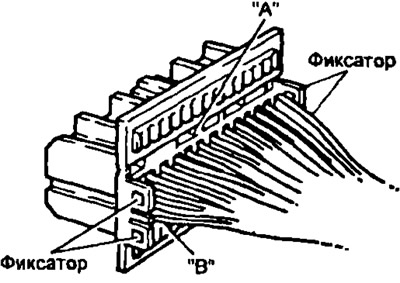
- b) Remove the clips as shown in the figure, which will allow easy connection of the tester probes.
Note: Be careful with elements "A" and "B" which can be easily broken, especially in cold weather.
- c) Reconnect the connectors to the electronic control unit.
Note:
- Make all voltage measurements with the connectors connected.
- The battery voltage must be at least 11 V when the ignition is on.
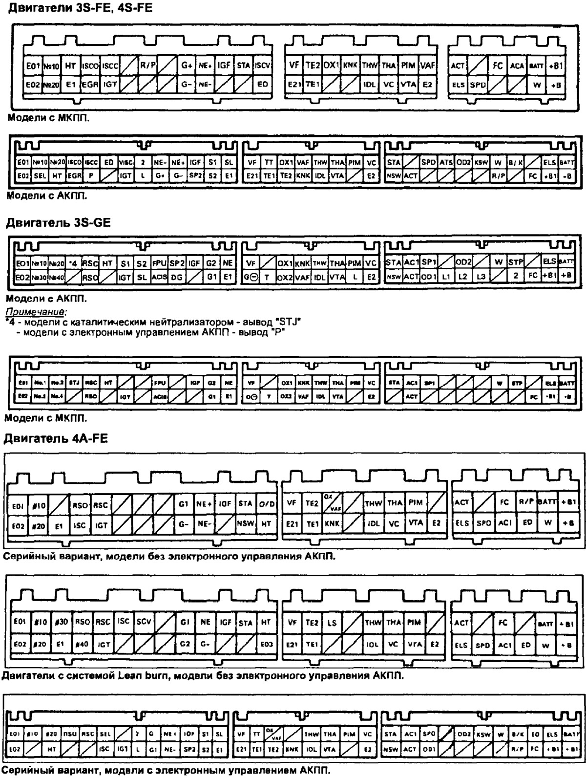
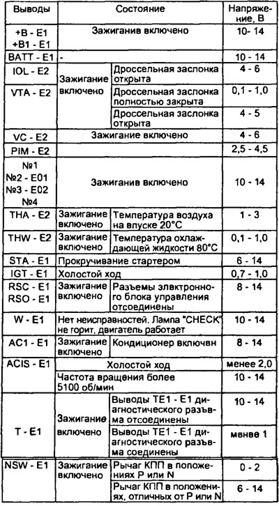
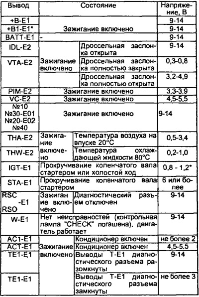
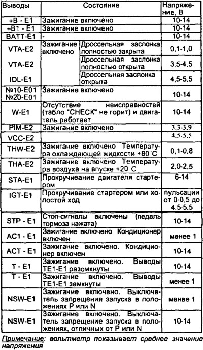
Using a voltmeter with high self-resistance (not less than 10 kOhm/V), measure the voltage at each terminal of the electronic control unit.
Electronic control unit outputs
Open a larger image in a new tab »
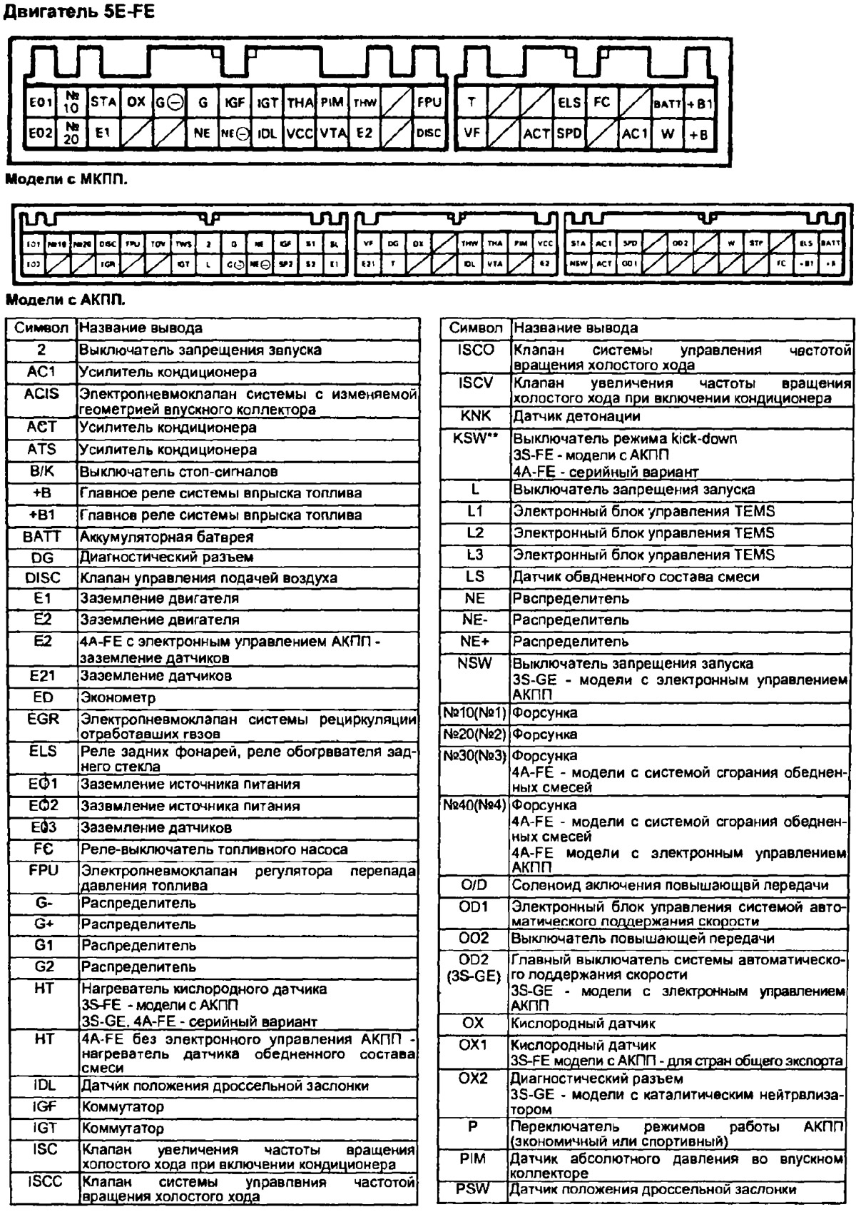
Open a larger image in a new tab »
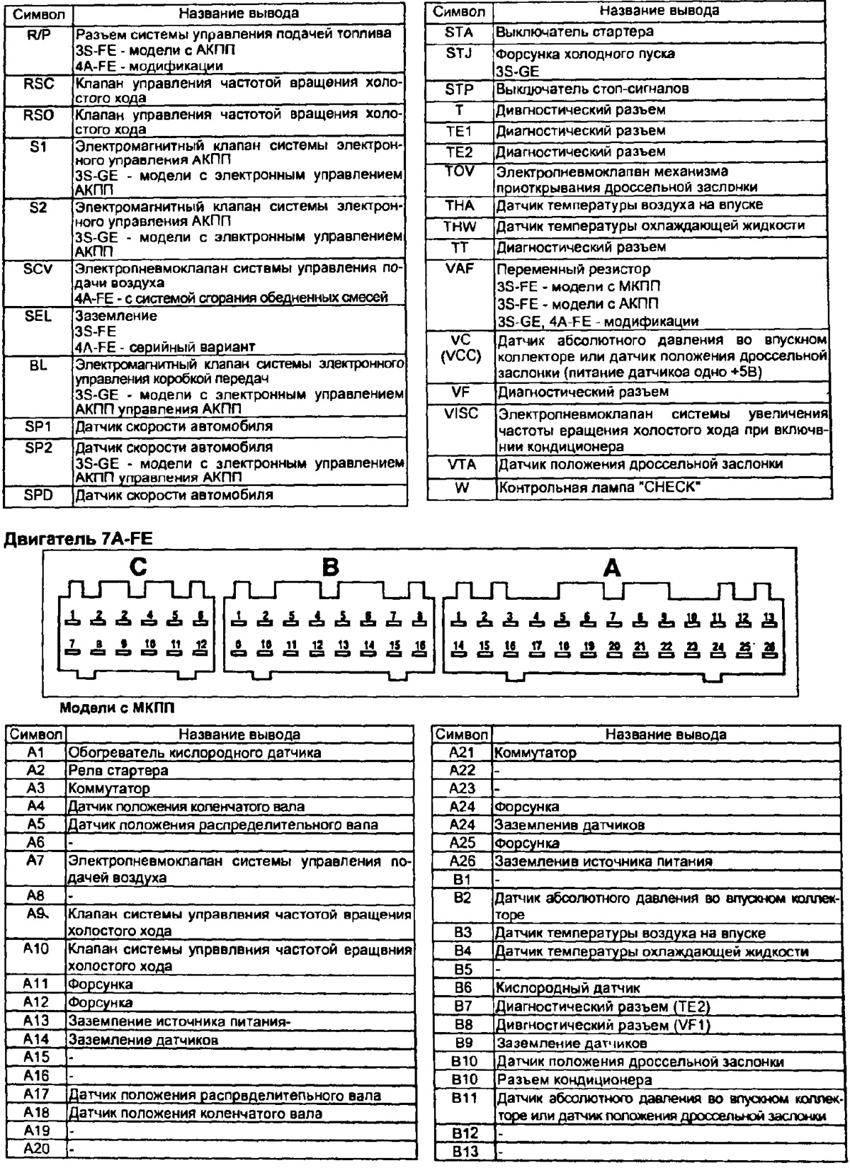
Open a larger image in a new tab »
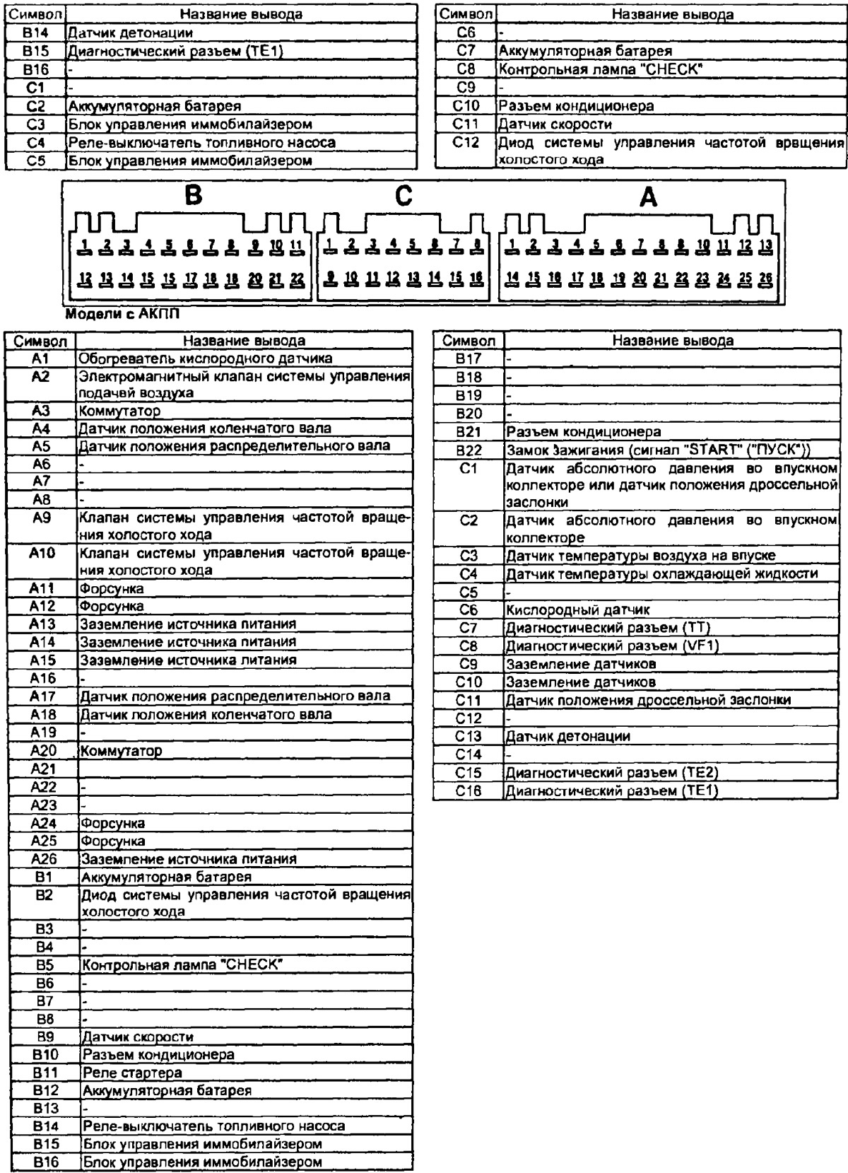
Open a larger image in a new tab »
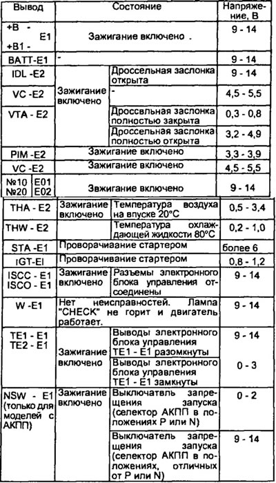
Voltage between terminals of the electronic control unit
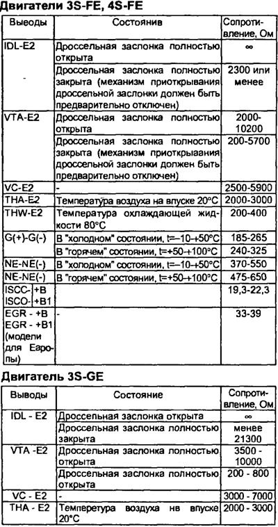
Engines 3S-FE, 4S-FE
Engine 3S-GE
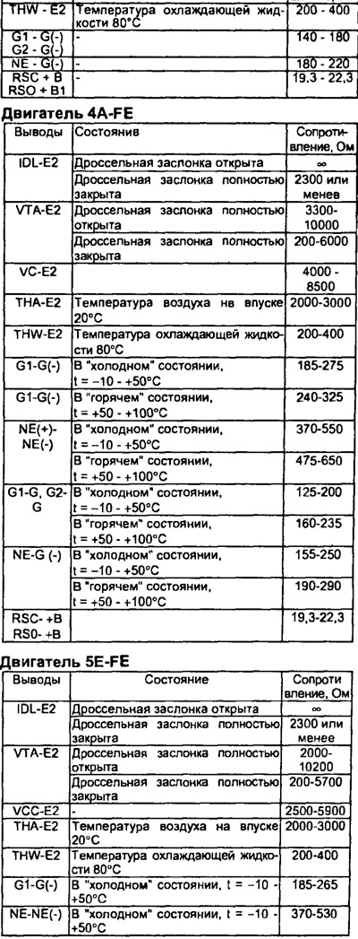
Engine 4A-FE
Engine 5E-FE
Resistance between terminals of the electronic control unit