
Description
The electronic control unit has a built-in self-diagnosis system, which continuously monitors the condition of the engine based on sensor signals. If a malfunction is detected, this system identifies it and informs the driver about it with a signal "CHECK" (check engine), which is highlighted by a control lamp located on the dashboard.
The self-diagnostic system of the 3S-FE, 4S-FE, 3S-GE, 4A-FE and 7A-FE engines has several modes of operation ' normal mode (current) self-diagnosis and test mode. When operating in the normal self-diagnosis mode, the electronic control unit analyzes various signals (see table of diagnostic codes below) and determines the failed system by the output parameters recorded by the corresponding sensors or actuators.
A warning light on the instrument panel informs the driver of a malfunction (however, codes are not displayed on the dashboard). The signal turns off automatically immediately after the malfunction has been eliminated. However, the electronic unit stores (remembers) fault codes in memory (except code no. 16), associated with the corresponding failures, until then. until the diagnostic system is cleared (Not "throw off" information) by disconnecting the fuse "EFI" with the ignition off The diagnostic code can be determined by the number of flashes of the control lamp "CHECK" with closed outputs "TE1" And "E1" diagnostic socket. If there are 2 or more faults, their indication starts from the smallest code (having the smallest number) and then continues in ascending order.
In test mode (testing) systems in the presence of malfunctions, the electronic control unit also lights up a signal lamp on the dashboard, additionally highlighting the codes of those malfunctions that are not detected in the normal mode (current) self-diagnosis (except for codes No. 42, 43 and 51). At the same time, the terminals "TE2" And "E1" diagnostic connector must be shorted as shown below.
In test mode, even after the malfunction has been eliminated, its code is stored in the memory of the electronic control unit after the ignition is turned off (except for codes No. 42, 43 and 51) similar to what takes place during the current self-diagnosis. Selecting the type of self-diagnosis ("current" or "testing") is carried out by the corresponding closure of the conclusions "TE1", "TE2" And "E1" The diagnostic connector, as will be shown below, The test mode is used when troubleshooting problems that are difficult to determine in normal mode (current) self-diagnosis (e.g. communication breakdown). Self-diagnosis during testing can be used by specialists, subject to the appropriate procedure for connecting the terminals of the diagnostic connector and a certain sequence of operations (see below).
Engine warning lamp "CHECK"
1. Malfunction indication control lamp "CHECK" - a warning light signal, which is a light panel on the instrument panel, lights up when the ignition is on and the engine is not running.
2. After starting the engine, the lamp "CHECK" should go out. If the indicator lamp continues to burn when the engine is running, this means that the diagnostic system warns of a malfunction.
Output of diagnostic codes (normal self-diagnosis mode)
To obtain an output diagnostic code, perform the following procedures.
1. Check the initial conditions.
- A) The battery voltage is at least 11 volts.
- b) Throttle valve - fully closed (sensor leads "IDL" throttle position - closed).
- V) Gearbox control lever - in neutral position (automatic transmission selector in position "R").
- G) All accessories in off position (OFF).
- d) The engine is warmed up to normal operating temperature.
2. Turn on the ignition, but do not start the engine. Pilot lamp "SNEC" should burn.
3 Short the leads "TE1" And "E1" diagnostic connector, the malfunction indicator lamp should go out and start flashing.
Note: if the flashing of the control lamp is not observed, then the conclusions of the diagnostic connector are not bridged.
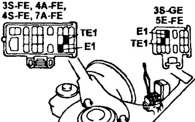
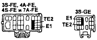
Diagrams of the location of the terminals of the diagnostic connector are shown in the figures.
4. Read the diagnostic code by the number of blinks (outbreaks) fault control lamp "CHECK ". (See the table below for diagnostic codes).
The type of diagnostic code depends on the type of electronic control unit and on the type of malfunction. On 4A-FE and 7A-FE engines, a TOYOTA computer engine control system is used with 2 types of electronic control unit, depending on the presence or absence of an air mass meter in the fuel injection control system. Diagnostic codes when using these control units differ in the duration of the pulses (the duration of each blink) and pulse duty cycle (time between flashes).
Form of diagnostic codes
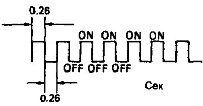
- A) Normal system operation (no fault) - The light panel of the control lamp lights up and goes out at an interval of 0.26 seconds.
- b) Fault code display. - If there is a fault, the lamp flashes every 0.52 seconds. The first sequence of flashes corresponds to the first number of the diagnostic code, which consists of two numbers. After a pause of 1.5 seconds, a second sequence of flashes is displayed, corresponding to the second number of the code. If there are two or more fault codes, an interval of 2.5 seconds is set between them when outputting.
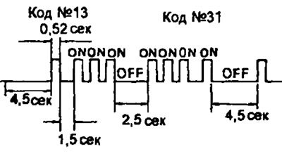
After all the codes are displayed, there is a pause of 4.5 seconds, and then they all repeat until the conclusions "TAG and "E1" diagnostic connector are short-circuited.
Note: In the case of several fault codes, their indication starts with a smaller code and continues in ascending order.
- V) (3S-FE, 4A-FE, 4S-FE, 5E-FE and 7A-FE) Electronic control unit with 2-stage fault detection algorithm.
The electronic control unit of these engines uses a two-stage fault detection algorithm.
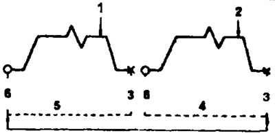
1 - fixing a malfunction for the first time (preliminary recording in memory), 2 - fault fixation for the second time (the control lamp lights up), 3 - ignition off, 4 - second cycle, 5 - first cycle, 6 - ignition switch on.
When writing codes "21" And "25" a two-stage algorithm is used. It consists in the fact that when a malfunction occurs for the first time, its code is temporarily stored in the memory of the electronic control unit. If the same malfunction is recorded during the second test driving test. then in this case the control lamp lights up. The second driving test is carried out again in the same mode. (However, the ignition must be switched off between the first and second test drive cycles).
During self-diagnosis in test mode (second mode of self-diagnosis system) the control lamp turns on at the first manifestation of a malfunction.
5. Upon termination of diagnosing disconnect a wire from a diagnostic socket.
Output of diagnostic codes (self-diagnosis in test mode)
Note:
- Compared to the normal self-diagnosis mode, the test mode self-diagnosis has additional capabilities for troubleshooting.
- This allows you to determine malfunctions in the electrical circuits of the starting system, the air conditioning system, as well as in the electrical circuit of the neutral position indicator on the gear lever ("switch" neutral).
- Moreover, self-diagnostics in the test mode allows you to identify faults that are also fixed by normal self-diagnosis.
To obtain a diagnostic output code in test mode, perform the following procedures.
1. Check the initial conditions
- A) The battery voltage is at least 11 volts.
- b) Throttle valve - completely closed.
- V) Gearbox control lever - in neutral position (automatic transmission selector in position "R").
- G) All accessories are off.
- d) The engine is warmed up to normal operating temperature.
2. Turn off the ignition (OFF).
3. Short-circuit the terminals with a suitable wire "TE2" And "E1" diagnostic socket.
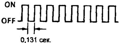
4. Turn on the ignition (ON), and the self-diagnosis system will operate in test mode.
Note. Confirmation that the self-diagnostic system is operating in test mode is the flashing of the control lamp "CHECK" with the ignition on. In this case, the time between the end and the beginning of successive pulses (outbreaks), that is, the duty cycle of the pulses, is 0.131 s.
5. Start the engine and drive the vehicle at a speed of 10 km/h or more.
6. Simulate the situations in which the customer describes the problem.
7. Bridge the contacts with a suitable wire "TE1" And "E1" diagnostic connector.
8. Read diagnostic codes by the number of flashes of the control lamp "CHECK".
9. At the end of the diagnosis, disconnect the wires from the diagnostic connector.
Note:
- The system will not enter test mode if the contacts "TE2" And "E1" will be bridged after the ignition is switched on.
- If you do not carry out the 4th stage of the test cycle.
- (road test), then the signals of the starting system (starter) and vehicle speeds will be recorded by the electronic unit as malfunctions, and codes No. 42 and Ns 43 will be displayed by the control pump.
- If the automatic transmission control lever is in the following positions: "D", "2", "L" or "R", or if enabled (ON) air conditioning, or if the accelerator pedal is fully depressed, code No. 51 is displayed ("turning on the air conditioner"), which, however, is not a sign of a malfunction.
Erasing a diagnostic code
1. After repair of a faulty node, the diagnostic code is stored in the memory of the electronic control unit Therefore, it must be deleted (erased) by disabling the EFI fuse of the injection system (with the ignition off). The fuse is located in the junction box. Shutdown time (at least 10 s) dependent on ambient temperature (the lower the temperature, the longer the fuse must be off).
Note:
- Erasing can also be done by turning off the negative (-) battery terminals. But in this case other systems with "memory" (clock, etc.) Also "clean up".
- If the diagnostic code is not erased, it will be stored in the memory of the electronic control unit and will appear along with a new code in the event of a future malfunction and mislead.
- If necessary, turn off (withdrawals) battery must first read the trouble codes.
2. After the erasing operation, you must perform a driving test and make sure that the indicator lamp "CHECK" the code 'normal operation' is displayed".
If the same diagnostic code is again displayed by the warning lamp "CHECK", which means that the repair work has not been carried out satisfactorily.
Diagnostic indication
1. The electronic control unit includes the following fault codes (see table below) and among them - the code for the normal operation of the engine.
2. If 2 or more types of malfunctions appear at the same time, then the code with the smallest number is displayed first, and then as the numbers increase.
3. All fault codes recorded in the road cycle are stored in the memory of the electronic control unit from the moment of registration until the moment of erasure ("reset"), except for codes No. 16, 43, 51 and 42 (4A-FE, 7A-FE); №16, 42, 43, 51 (3S-FE, 4S-FE); №16, 51.53 (3S-GEJ and #51 (SE-FE).
4. After troubleshooting, trouble codes are not displayed using the warning lamp "CHECK", but are stored in the memory of the electronic control unit, with the exception of the code numbers indicated in the previous paragraph.