



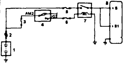
Injection system main relay connection diagrams: 1 - Battery, 2 - Main fuse 2.0L, 3 - AM2 fuse (30 A), 4 - Ignition switch, 5 - EFI fuse (15 A), 6 - IGN fuse (7.5 A), 7 - Main fuel injection system relay, 8 - Electronic control unit
1. Remove the relay box cover and the main relay of the injection system.
2. Check the resistance of the relay winding.
- a) Using an ohmmeter, check for conductivity between terminals "1" and "2".
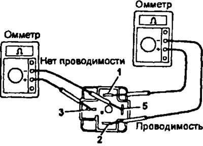
- 6) Then, using an ohmmeter, make sure there is no conductivity between terminals "3" and "5".
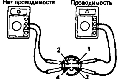
3S-GE, 5E-FE
- a) Using an ohmmeter, check for conductivity between terminals "1" and "3".
- b) Then, using an ohmmeter, make sure there is no conductivity between terminals "2" and "4".
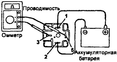
3. Check the operation of the relay.
3S-FE, 4A-FE, 4S-FE and 7A-FE
- a) Apply voltage from the battery to terminals "1" and "2" of the relay connector.
- b) Using an ohmmeter, check for conductivity between terminals "3" and "5".
If the conditions specified in points 1 and 2 are not met, replace the relay.
3S-GE, 5E-FE
- a) Apply voltage from the battery to terminals "1" and "3" of the relay connector.
- b) Using an ohmmeter, check for conductivity between terminals "2" and "4".
All engines
If necessary, the relay housing can be removed and, before throwing it away, try to eliminate the cause of the failure. To do this, clean all contacts and check the resistance of the windings in both directions, since there may be diodes that shunt the windings. If the resistance of the windings in both directions is the same, there are no diodes, then the battery can be connected in any order. If not, then the battery should be connected observing the polarity.
4. Install the relay and relay box cover.