



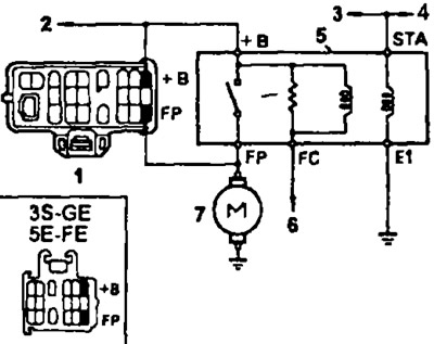
Fuel switch relay connection diagrams: 1 - diagnostic connector, 2 - to the electronic control unit; to the main relay of the fuel injection system, 3 - to the ignition switch (models with manual transmission); to the start inhibit switch (models with automatic transmission), 4 - to the electronic control unit (terminal "STA"), 5 - fuel pump switch relay, 6 - to the electronic control unit (terminal "FC"), 7 - fuel pump
1. Remove the fuel pump switch relay.
2. Check the relay's electrical circuit using an ohmmeter
- a) Check for conductivity between terminals: "STA" and "E1", "+B" and "FC".
- b) Check for conductivity between terminals: "+B" and "EP".
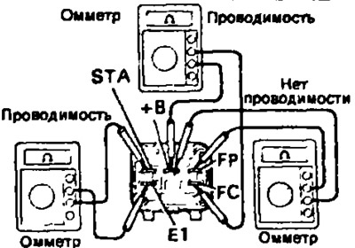
If the above conditions are not met, replace the relay.
3. Check the operation of the turntable.
- a) Apply voltage from the battery to the terminals "STA" and "E1" and use an ohmmeter to check for conductivity between the terminals "+B" and "FP".
- b) Apply voltage from the battery to the "+B" and "FC" terminals and use an ohmmeter to check for conductivity between the "+B" and "FP" terminals.
If the relay operation is not as described, replace the relay.