
Checking the main relay (1988-89)
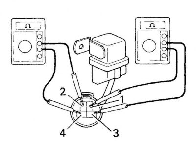
1, 2, 3, 4. Contacts
Checking the main relay (after 1990)
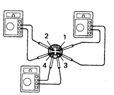
1, 2, 3, 4. Contacts
Checking the fuel pump relay
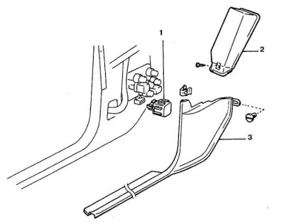
1. Fuel pump relay
2. Knee pad
3. Sidewall
1. Two relays are included in the electrical circuit of the fuel system. Check for battery voltage first at the main relay and then at the fuel pump relay.
2. Disconnect the main relay from the connector, then turn on the ignition (do not start the engine) and check for battery voltage.
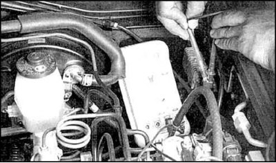
3. If there is battery voltage, replace the main relay and check for battery voltage at the fuel pump relay. The relay is located on the mudguard of the wheel well on the driver's side.
4. If battery voltage is present at both relays, check the relays themselves.
Main relay
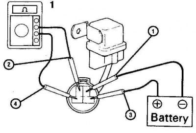
Checking the main relay with contact energization (1988-89)
1, 2, 3, 4. Contacts
1. Ohmmeter
Checking the main relay with contact energization (after 1990)
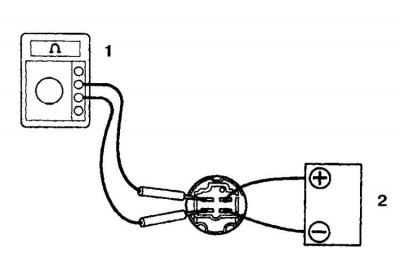
1. Ohmmeter
2. Battery
1. Using an ohmmeter, check continuity between pins 1 and 3 (see fig. Checking the main relay with contact energization (1988-89)). Between pins 2 and 4, the ohmmeter should show a gap.
2. Apply battery voltage to pins 1 and 3.
3. There must be a closed circuit between pins 2 and 4.
4. If the test results differ, replace the relay.
Turning on the fuel pump
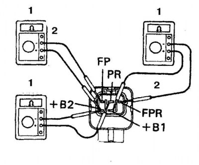
1. Ohmmeter (1) check the continuity of the circuit (2) between pins +B1 and FPR and +B2 and FP.
2. Between the +B and PR contacts, the ohmmeter should show a break.
3. Apply battery voltage to the +B1 and FPR terminals.
4. There should now be a closed circuit between the +B and FP pins. If the test results differ, replace the relay.
Fuel pump relay (1996)
Checking the fuel pump relay with coil energization
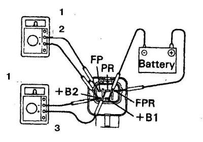
1. Ohmmeter
2. Closed circuit
3. Battery
Checking the fuel pump relay (1996)
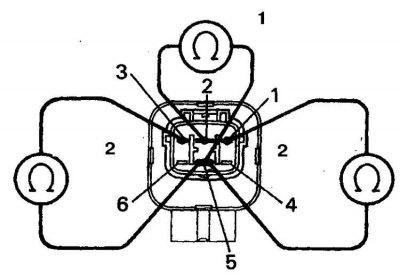
1, 2, 3, 4, 5, 6. Contacts
1. Open circuit
2. Closed circuit
1. There must be a closed circuit between pins 3 and 5 (see fig. Checking the fuel pump relay (1996)).
2. Between pins 3 and 5, the ohmmeter should show a resistance of 80 ohms.
3. Apply battery voltage to pins 1 and 5.
4. There should be battery voltage between pins 1 and 2, and a closed circuit between pins 3 and 5.
5. If the test results differ, replace the relay.
Fuel pump circuit relay (1988-94)
Fuel Pump Circuit Relay Test with Coil Energization (1988-94)
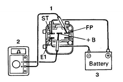
1. Ohmmeter
2. Closed circuit
3. Battery
1. Check for continuity between terminals ST and E1 (see fig. Fuel Pump Circuit Relay Test with Coil Energization (1988-94), as well as between pins +B and FC.
2. The ohmmeter should show a break between the +B and FP terminals.
3. Apply battery voltage to terminals ST and E1.
4. There must be a closed circuit between the +B and FP terminals. If the test results differ, replace the relay.
Fuel pump circuit relay (1995)
The test procedure is similar to the test of the main relay (see above).
Pump resistor resistance
1. The resistance of the pump resistor should be 0.73 ohm at normal temperature.
2. Otherwise, replace the resistor.