
- A) Disconnect the sensor connector.
- b) Turn on the ignition.
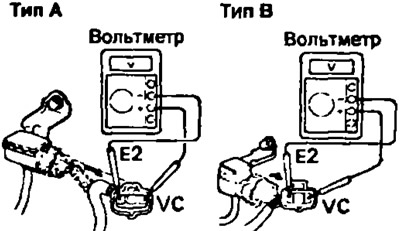
Using a voltmeter, measure the voltage between the terminals of the sensor connector: "VC' (conclusion "VCC" - 3S-GE) And "E2". Rated voltage:
- 3S-FE. 4A-FE, 4S-FE - 4.6-5.5 V
- 3S-GE. 5E-FE - 4.0-6.0 V
- 7A-FE (at idle) - 5.0 V
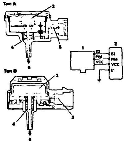
Sensor diagram and its connection diagram: 1 - absolute pressure sensor in the intake manifold, 2 - electronic control unit, 3 measuring chamber, 4 - filter, 5 - electrical contact, 6 - from the intake manifold
3S-FE, 4A-FE, 4S-FE and 7A-FE | 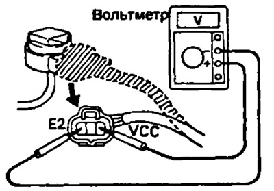
3S-GE, 5E-FE |
2. Check the output signal of the absolute pressure sensor.
- A) Turn on the ignition.
- b) Disconnect the vacuum hose from the intake manifold.
- V) Connect a voltmeter to the terminals "R1M" And "E2" connector of the electronic control unit and measure the output signal voltage at atmospheric pressure. Rated voltage 7A-FE - 3.6 V.
- G) Apply vacuum to the sensor in steps ranging from 13.3 kPa (100 mmHg) up to 66.7 kPa (500 mmHg).
- d) Measure the voltage drop for each vacuum value.
| Vacuum, kPa (mmHg.) | Voltage drop, V |
| 13,3 (100) | 0,3-0.5 |
| 26,7 (200) | 6,7-0,9 |
| 40,0 (300) | 1,1-1,3 |
| 53,3 (400) | 1.5-1.7 |
| 66,7 (500) | 1,9-21 |