
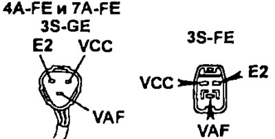
Disconnect the connector, turn on the ignition and measure the voltage between the terminals of the electronic control unit with a voltmeter "VCC" (or "VC") And "E2" (or "E21").
- 3S-FE, 4S-FE and 7A-FE: 4.5-5.5V
- 4A-FE, 3S-GE: 4.0-6.0V
2. Check the variable resistor output.
- A) Turn on the ignition.
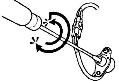
- b) Connect a voltmeter to the leads "VAF" And "E2" electronic control unit, and then slowly turning the adjusting screw of the variable resistor (mixture adjustment screw) first counter-clockwise to the stop, and then fully clockwise, measure the voltage between the terminals.
- V) Make sure the voltage gradually changes between 0-5V.
Note: There should be no voltage spike to 5V or a sudden drop to 0V.
3. Check the resistance of the variable resistor.
- A) Disconnect the resistor connector.
- b) Measure the resistance between terminals with an ohmmeter "VCC" (or "VC") And "E2" (or "E21") resistor connector. Rated resistance: 4-6 kOhm
- V) Fully turn the resistor adjustment screw (screw "quality") counterclock-wise.
- G) Connect an ohmmeter to the terminals of the resistor connector "VAF" And "E2". Turn the resistor slider fully clockwise and check that the resistance value changes from approximately 5 kΩ to 0.
- d) Connect the variable resistor connector.