
General information
Typical layout of ABS components
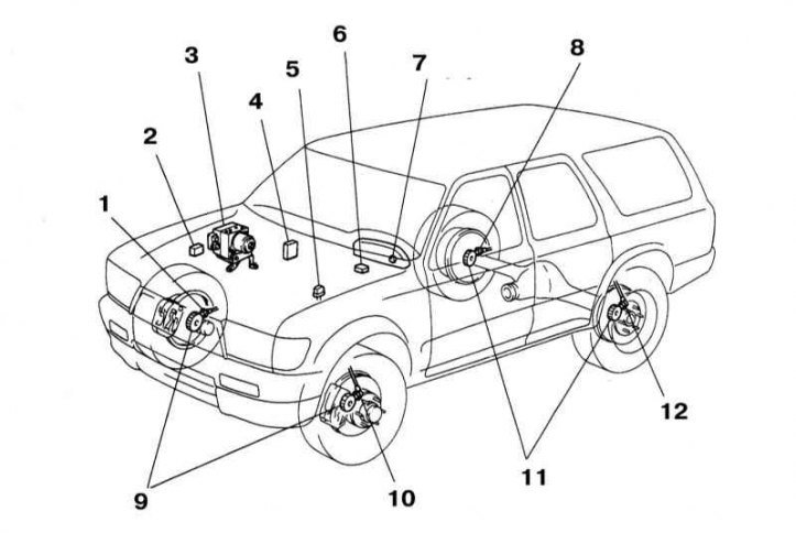
1 - Wheel sensor; 2 - ABS relay; 3 - ABS hydraulic modulator; 4 - ABS ECU; 5 - Diagnostic connector DLC 1; 6 - Deceleration sensor; 7 - Control lamp ABS; 8 - Wheel sensor; 9 - wheel sensor rotor; 10 - Wheel sensor; 11 - Rotors of wheel sensors; 12 - Wheel sensor
A sharp depressing of the foot brake pedal on a vehicle equipped with a conventional brake system causes the wheels to lock. In this case, the grip of the tread with the road surface is disturbed, and the car can go skidding, losing controllability. Anti-lock brake system (ABS) (refer to illustration above) prevents premature blocking of the wheels by continuously controlling the speed of their rotation during braking by modulating the pressure of the hydraulic fluid in each of the brake mechanisms.
Electronic control unit (ECU) ABS
The ABS ECU is located under the front door sill on the right door.
The ECU monitors the rotation speed of each of the vehicle's wheels based on input from the wheel sensors. When, during emergency braking, any of the wheels begins to lock up prematurely, the ECU issues a command to activate the solenoid valve placed inside the hydraulic modulator, which, when activated, opens the corresponding section of the brake circuit, releasing part of the working fluid from it into the reservoir and, accordingly, reducing the working pressure. As soon as the wheel speeds equalize, the valve closes again and the pressure continues to rise. The cycle lasts a fraction of a second on each of the wheels and repeats until the braking is completed. The design of the system allows you to adjust the pressure in the hydraulic circuits of each of the four wheels. In reality, the ABS operation is much more complicated than it might seem, so the compilers of this manual do not recommend car owners to attempt to repair the system on their own. In the event of a problem, it would be wiser to contact a car service specialist.
Hydraulic modulator
The modulator is installed inside the engine compartment and is equipped with an ECU-activated solenoid valve for adjusting hydraulic pressure in the brake circuits.
Wheel sensors
Each of the wheels is equipped with an individual speed sensor. The sensor consists of a rotor (rings with teeth evenly spaced around its perimeter) and a sensitive element in the form of a magnetized coil. The sensitive element of the sensor captures the moments when the teeth of the rotor pass by it and converts the information received into electrical signals that are continuously transmitted to the ABS control module. Based on the results of processing the incoming signals, the ECU receives information about the relative speed of rotation of each of the wheels. As long as all four wheels rotate at the same speed, ABS is in a passive state. As soon as any of the wheels starts to block, the control unit detects the change in the input signal and generates a command to operate the modulator, which instantly relieves the pressure of the hydraulic fluid in the brake mechanism of the corresponding wheel.
Brake light switch
Based on the signals from the brake light switch, the ECU detects the moment when the driver depresses the foot brake pedal, immediately activating the ABS.
Diagnostics and refurbishment
If the ABS warning light built into the vehicle's instrument panel comes on and stays on while driving, first make sure that the parking brake is fully released and that the brake system is functioning properly. If everything is normal, then the ABS has failed. In this case, a fault code must be entered in the ECU memory. When diagnosing and reading fault codes, the warning light on the instrument panel will flash. If there are several codes, their indication will start from the lower number in ascending order, regardless of the time of their receipt. When the car is moving, the fault codes are not displayed. Perform a visual inspection:
- Check the condition of the brake calipers and wheel cylinders;
- Check the condition and reliability of fastening of contact r
- ECU wiring connectors and wheel sensors (see Onboard electrical equipment);
- Check the relevant fuses (see Onboard electrical equipment).
ABS refurbishment is beyond the skill of the average amateur mechanic.
Reading and erasing fault codes
1. Turn the ignition key to the OFF position. Check the condition of the battery; The system requires at least 12V to operate.
2. Switch on the ignition and check that the ABS warning lamp on the instrument panel lights up. If the light does not come on, check the fuse, the light or the wiring.
3. Use a jumper to short the Ec and E1 pins on the DLC1 connector. Turn on the ignition.
4. If there is a fault code in the memory, after 4 seconds the light will flash. The number of the first burst of flashes indicates the number of tens of the two-digit fault number, followed by a pause of 1.5 seconds, and the second burst of flashes is transmitted, indicating the number of ones of the two-digit number. If other fault codes are present in the system, they will be transmitted sequentially at 2.5 second intervals. After the end of reading the codes, they will all be repeated in the same sequence after four seconds. If there are no DTCs, the light will flash every 1/2 second without variation.
5. Turn the ignition key to the OFF position.
6. Check the system or repair it in accordance with the received fault codes.
7. After repair, it is necessary to erase the fault codes from the memory. If the battery was disconnected during the repair process, all fault codes will be erased automatically. Fault codes are cleared by pressing the brake pedal 8 or more times within 3 seconds.
8. Remove the jumper and connect the process connector to the actuator.