
Location of anti-lock brake system units (ABS systems)
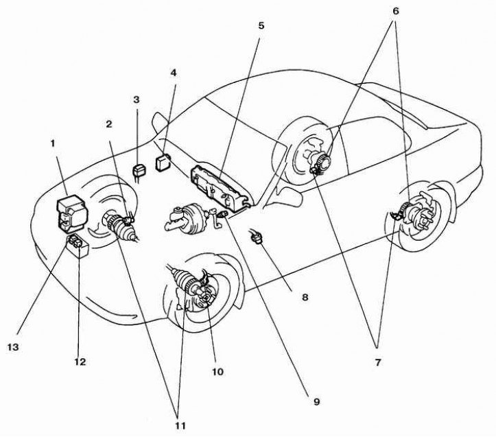
1. Actuator; 2, 10. Front speed sensors; 3. Diagnostic connector (DLC1); 4. Control unit; 5. Indicator lamp for the health of the ABS system; 6, 11. Speed sensor rotors; 7. Rear speed sensors; 8. Diagnostic connector (DLC1); 9. Stop signal switch; 12. ABS motor relay; 13. Traction relay solenoid valve
ABS system units
Actuator
The actuator consists of a master cylinder, an electro-hydraulic pump and 4 solenoid valves.
Attention! ABS systems are supplied by Bosch and Nippondenso. The Bosch system actuator has a monobloc design and contains an integrated processor control unit and a solenoid valve relay, while in the Nippondenso system these components are mounted separately.
The electric pump is designed to pump fluid into the actuator receivers, through which fluid is supplied under pressure to the brake circuit.
Solenoid valves control the pressure in the brake circuit when the ABS system is activated, the valve block contains 4 valves, 1 valve per wheel.
Wheel speed sensors
Rotary type sensors mounted on each of the wheels. The signals from the sensors are sent to the control unit.
The front sensors are mounted on the steering knuckle, next to the toothed rings of the rotors. The rotors are structurally integrated with the front outer CV joints of the axle shafts.
The rear sensors are mounted on the rear axle brackets, the rotors are structurally integrated with the rear hub.
Abs control unit
The Nippondenso system control unit is mounted under the front bulkhead, the Bosch system control unit is mounted in the actuator. The unit receives signals from the brake light switch and speed sensors for each wheel. These signals are the initial data for adjusting the pressure in the hydraulic drive of this wheel. The control unit also has the function of self-diagnosis and failure storage.
If the system fails, the control lamp on the instrument panel lights up, and a failure code is stored in the memory, which can be read and determine the nature of the malfunction or a faulty unit.
Diagnostic codes
The fault code is stored in memory until the contents of the memory cells are erased, or until the fault is eliminated.
When the ignition is switched on, the ABS warning lamp lights up, and goes out after the engine is started. If the lamp continues to burn, then a malfunction has been registered in the ABS system.
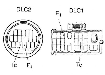
To access fault codes, turn the ignition key to the OFF position (engine not running). In the Nippondenso system, remove the jumper (see photo) diagnostic connector pins. On both types of systems, bridge the terminals E1 and Tc of the connector, turn the ignition key to the ON position (engine not running) and read codes.
Nippondenso ABS Diagnostic Connector Jumper
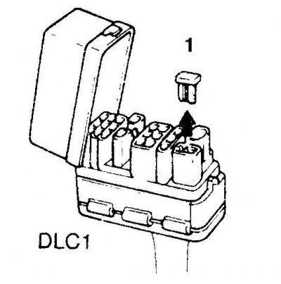
1. Jumper
Jumper pins on two types of used diagnostic connectors
The numbers of the two-digit code are determined by the number of flashes of the control lamp, separated by a pause of 1.5 seconds (for example code 34 - 3 flashes, pause 1.5 seconds and 4 flashes).
Following code (if there is another problem) appears 2.5 seconds after the first. If the system is working, the lamp flashes with a period of 0.5 s.
Determine the nature of the failure according to the attached table.
After reading, erase the codes, to do this, bridge the terminals E1 and Tc of the connector, turn the ignition key to the ON position (engine not running) and press the pedal at least 8 times within 5 seconds. Remove the jumper and replace the connector cover. Take the car to a car service.
Table of ABS system failure codes
Code | Nature of the fault | Actions taken |
11 | An open in the solenoid relay circuit | Check solenoid valve relay and relay circuit wiring |
12 | Short circuit of the solenoid valve relay circuit | Same |
13 | An open in the pump motor relay relay circuit | Check pump relay and relay circuit wiring |
14 | Short circuit of the pump motor relay circuit | Same |
21 | Faulty right front wheel solenoid circuit | Check actuator solenoid and circuit |
22 | Faulty left front wheel solenoid circuit | Same |
23 | Faulty right rear wheel solenoid circuit | Same |
24 | Faulty left rear wheel solenoid circuit | Same |
25 | Open or short in SMC1 circuit | Check system actuator and circuit |
26 | Open or short in SMC2 circuit | Check system actuator and circuit |
27 | Open or short in SRC1 circuit | Check system actuator and circuit |
28 | Open or short in SRC2 circuit | Check system actuator and circuit |
31 | Faulty right front wheel speed sensor | Check speed sensors, wiring and sensor connector |
31 | No signal from right front wheel speed sensor | Check speed sensor, wiring and sensor connector |
32 | There is no signal from the left front wheel speed sensor | Same |
33 | There is no signal from the right rear wheel speed sensor | Same |
34 | There is no signal from the left rear wheel speed sensor | Same |
35 | Open in the right front wheel speed sensor circuit | Same |
36 | An open in the left front wheel speed sensor circuit | Same |
37 | The number of teeth of the rotor of the speed sensor does not correspond to the normal | Check the health of the sensor rotor (all teeth present) |
38 | An open in the right rear wheel speed sensor circuit or in the sensor itself. | Check speed sensor, wiring and sensor connector |
39 | An open in the left rear wheel speed sensor circuit or in the sensor itself | Check speed sensor, wiring and sensor connector |
41 | Battery voltage too low | Check charge system: alternator (see subsection 3.4.10), battery (see subsection 3.4.9), voltage regulator (see subsection 3.4.11). |
43 | Failure of the brake release control system | Check all ABS wires and connectors |
44 | Open or short in NE signal circuit | Check all wires and connectors from the ABS control unit |
49 | An open in the brake light switch circuit or in the switch itself | Check switch and switch circuit |
51 | Actuator motor blocked | Check for short circuit in motor and relay circuit, check battery |
53 | PCM circuit failure | Check all wires and connectors from the ABS control unit |
58 | An open in the brake light switch circuit or in the switch itself | Check switch and switch circuit |
61 | Failure of the engine management system | Check Engine Management System Fault Codes (see subsection 7.2.) |
62 | Control unit failure | Repair or replacement of the control unit is required |
The lamp is on continuously | Control unit failure | Repair or replacement of the control unit is required |