



Brake master cylinder
Removal
1. On models prior to 2000, remove the air cleaner housing cover (see chapter 4A or 4B) and the relay/fuse block from the left "cup" of the pillar.
2. Disconnect the wiring connector from the fuel level alarm contact sensor (see Figure 8.2).
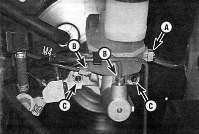
Figure 8.2. Brake master cylinder components:
A - Wiring connector;
B - Brake pipe fittings;
C - Fastening nuts.
3. Pump out as much fluid as possible from the master cylinder reserve reservoir using a large syringe.
4. Place rags under the fittings and have caps or plastic bags available to cover the openings of the tubes after disconnection. Loosen the brake line fittings where they connect to the master cylinder. To avoid rounding the edges, use a special open-end wrench that grips the fitting tightly.
Warning. When brake fluid comes into contact with painted surfaces, it leaves stains that are difficult to remove. Immediately rinse off any liquid splashes with plenty of clean, cold water; whenever working in the engine compartment, cover the vehicle's fenders with protective covers.
5. Move the brake pipes slightly away from the master cylinder and plug the resulting holes to prevent dirt from getting in.
6. Unscrew the two nuts securing the master cylinder to the vacuum booster. Remove the master cylinder from the studs, being careful not to spill any brake fluid. Remove and discard the old gasket between the master cylinder and the booster. Check the condition of the master cylinder O-ring and replace it if it is cracked or hardened.
Installation
Note: Before installing a new or remanufactured master cylinder, check the clearance between the booster rod and the bottom of the master cylinder piston seat. If necessary, adjust the length of the vacuum booster rod (see paragraph 15).
7. Bleed the new master cylinder on the workbench. To do this, clamp it in a vice by the mounting flange.
(The original article is on the portal: TOYOTAMAN.ru)
8. Connect a pair of bleeder hoses to the cylinder outlet fittings and immerse them in the reserve reservoir with brake fluid (see figure 8.8).
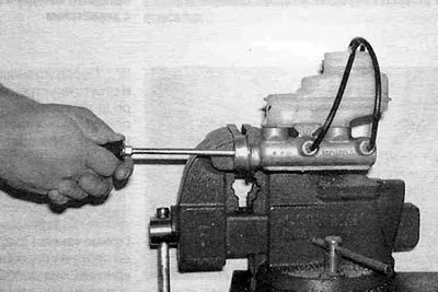
Figure 8.8. To remove air, attach a pair of bleeder hoses to the cylinder outlet fittings and immerse them in the reserve tank.
9. Fill the master cylinder reservoir with the recommended type of brake fluid (see "Weekly checks").
10. Gently push the pistons into the cylinder (you can use a large Phillips screwdriver) - air will escape into the reserve tank. Since the hoses are immersed in liquid, no air will enter the cylinder when the pistons are released.
11. Repeat the procedure until the bubbles stop coming out.
12. Remove the hoses one by one, plugging the holes with plugs to prevent fluid leakage and air from entering the cylinder. Replace the reservoir cap.
13. Install the master cylinder onto the booster studs and hand tighten the mounting nuts. Don't forget to install a new gasket.
14. Carefully watching the thread entry, tighten the nuts of the tube fittings, carefully tighten them, being careful not to strip the threads.
15. Tighten the mounting nuts to the specified torque Specifications of this chapter. Tighten the threaded connections of the fittings securely.
16. Connect the wiring connector to the emergency fuel level sensor.
17. Fill the reserve reservoir with brake fluid and bleed the master cylinder and brake system as described in paragraph 10. The master cylinder can also be bled on the vehicle. Since it is quite difficult for one person to simultaneously pump the brake pedal and watch for bubbles to come out of the cylinder, an assistant will be needed. Ask an assistant to gently press the brake pedal and hold it in this position. Loosen the fitting of the first tube and let the liquid and air flow out (see Figure 8.17).
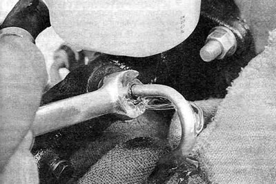
Figure 8.17. Ask an assistant to gently press and hold the brake pedal. Loosen the fitting of the first tube and let the liquid and air flow out. Repeat this procedure until the bubbles stop coming out.
Repeat this procedure until the bubbles stop coming out. Make sure there is fluid in the reservoir to prevent air from being sucked into the cylinder from there. Before starting normal operation of the vehicle, carefully check the operation of the braking system on a deserted road.
Replacement of the reserve tank/sealing bushings
Note: If the master cylinder reservoir is damaged, it can be replaced separately from the master cylinder body. If there is a fluid leak between the reserve tank and the cylinder body, the reserve tank sealing bushings can also be replaced.
18. Pump out as much fluid as possible from the master cylinder reserve reservoir using a large syringe.
19. Place a rag under the master cylinder to collect any brake fluid that may spill when the reservoir is disconnected from the master cylinder.
Warning. When brake fluid comes into contact with painted surfaces, it leaves stains that are difficult to remove. Rinse off splashes immediately with plenty of cold water; when working under the hood, cover the car's fenders with protective covers.
20. Loosen the screw securing the reserve tank to the master cylinder.
21. Remove the reserve tank from the master cylinder body.
22. Remove the sealing bushings from the master cylinder (see Figure 8.22).
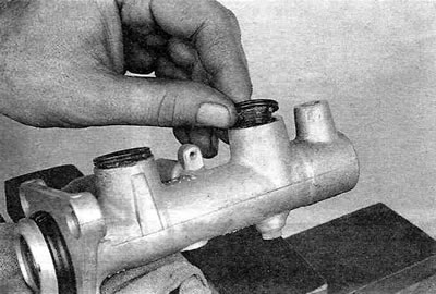
Figure 8.22. After removing the reserve tank, remove the sealing bushings from the master cylinder housing. If the bushings are hardened, cracked or leaking, replace them.
23. Lubricate the new sealing bushings with clean brake fluid, then press them into the cylinder.
24. Place the tank on the bushings and tighten the fastening screw.
25. Fill the reservoir with the recommended type of brake fluid (see "Weekly checks") and make sure there are no leaks.
26. Bleed the master brake cylinder (see Figure 8.17), then bleed the rest of the hydraulic brake system (see paragraph 10).