



Checking and replacing high-voltage wires, distributor cap and rotor

Note: Only 1996 and 1997 models are equipped with traditional ignition distributors. Ignition systems on models produced from 1998 to 2000 do not have contact distributors. All models produced since 2000 use high-voltage wires. All models produced since 2001 have an ignition system of the type "coil-over-plug", in which each spark plug has its own ignition coil attached directly to it. Therefore, the procedure described below does not apply to models produced since 2001.
1. High voltage wires should be checked regularly and every time the spark plugs are replaced.
2. Begin this procedure by visually inspecting each wire with the engine running. In a darkened garage (necessarily ventilated) start the engine and inspect each wire. Be careful not to touch moving engine parts. If the insulation is damaged, you will see an electric arc or small bluish sparks at the damaged areas. Sparking indicates that the high-voltage wires need to be replaced. Turn off the engine, let it cool down and proceed to check the distributor cap and rotor.
3. High voltage wires should be checked one by one to avoid making a mistake when connecting. The order of connecting the wires is very important for the proper operation of the engine. Each original ("native") wire should have a number to determine its location. If the numbers are indistinguishable, it makes sense to number the wires using known methods.
4. Disconnect the high-voltage wire from the spark plug and from the ignition coil terminal. Pull only by the tip of the wire, twisting it gently, and never by the wire itself.
5. Inspect the inside of the cap. Clean off any possible corrosion in the form of white deposits. Do not confuse it with insulating grease, which is used to prevent corrosion.
6. Place the wire on the spark plug. The wire on the spark plug must be securely fixed. If the wire does not hold on to the spark plug, remove it and use pliers to press the metal contact inside the cap so that it snaps onto the spark plug contact.
7. Wipe the wires, removing dirt from them along their entire length. The wires must not have any cracks, burns or other damage. The insulation must be elastic. Repeat the above procedure with the remaining wires.
8. Using a small screwdriver, pry up the spring clip (if there is one, see Figure 26.8), disconnect the high-voltage wire from the distributor cap (models produced before 1997) or coil block (models produced from 1998 to 2000).
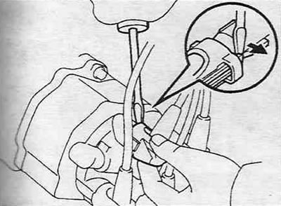
he 26.8. Using a small screwdriver, pry up the spring clip and disconnect the rubber cap of the high-voltage wire from the distributor cap.
Check for tight fit and absence of corrosion. Reconnect the wire.
9. Check the remaining high-voltage wires and ensure that the tips are correctly seated on the coil pack terminals and spark plugs.
10. If replacement of wires is required, the entire kit must be purchased. Replace the wires one at a time to avoid mixing up the firing order.
11. Remove the distributor cap (models produced before 1997), unscrewing the mounting bolts (see Figure 26.11,a).
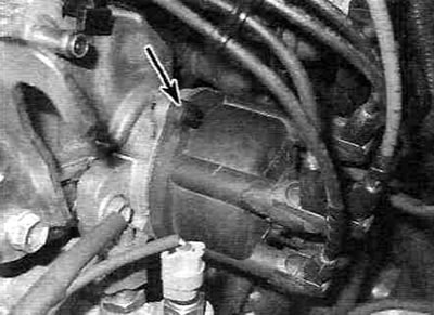
Figure 26.11,a. Unscrew the mounting bolts (the top bolt is shown, the bottom one is not visible) and remove the distributor cap.
Inspect the inside of the cap and ensure there are no cracks, carbon dust, or worn, burnt, or loose contacts (see Figure 26.11,b).
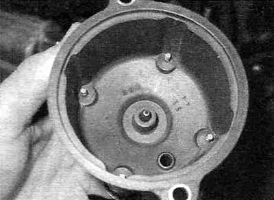
Figure 26.11, b. Inspect the inner surface of the lid and make sure there are no carbon particles, burnt, worn or loose contacts, or other defects.
If at least one of the listed defects is detected, replace the cover.
12. Loosen the mounting bolts and remove the distributor rotor (see Figure 26.12,a).
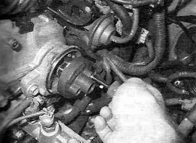
26.12,a. The distributor rotor is secured with bolts.
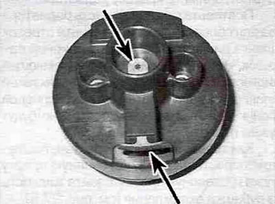
Figure 26.12,b. Inspect the rotor and make sure there is no damage, corrosion or wear on the contacts.
Check for cracks, damage or carbon particles. If any of these defects are present, replace the cover and rotor.
13. As a rule, the distributor cap and rotor are replaced at the same time as the high-voltage wires. Measure the resistance of the high-voltage wires to the internal contact in the cover, as shown in Figure 26.13.
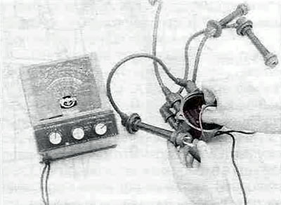
Figure 26.13. Measure the resistance of high-voltage wires.
If the resistance is greater than that specified in Specifications, replace the cover and/or wires.
14. When installing a new cover, disconnect the wires from the old one one by one, immediately installing it on the new cover in strict accordance with the numbering, so as not to confuse the firing order.