



Injectors
Examination
1. The resistance of the injector windings can be checked without removing the injectors from the engine. First, remove the intercooler and upper engine covers.
2. Disconnect the wiring connectors from the injectors.
3. Connect an ohmmeter to the terminals of each injector one by one and check the resistance value for compliance with the specification standards.
4. Now use an ohmmeter to measure the resistance between the injector terminals and the body. "Chains" (electrical conductivity) it shouldn't be.
5. If the resistance value does not match the specified value, replace the injector.
Removal
6. Loosen the coolant expansion tank mounting bolts at the front of the engine compartment and remove it, then set it aside.
7. Release the engine wiring harness from the fasteners near the fuel rail.
8. Remove the high pressure fuel lines as described in the previous paragraph. Tape or plug any holes in the pipes, injectors, and fuel rail to prevent dust and dirt from entering the fuel system.
Note: Toyota recommends that when replacing the fuel rail and/or injectors, also replace the high-pressure fuel lines that feed the injectors, and when replacing the injection pump or fuel rail, also replace the fuel inlet line (line).
9. Remove the lower clamps securing the injector feed tubes from the intake manifold housing.
10. Remove the valve cover as described in chapter 2B.
11. Place a rag under the fuel return line to collect any spilled fuel.
12. Loosen and remove the union bolt on the fuel return line on the timing belt side and remove the double sealing washer.
13. Unscrew the four hollow bolts securing the return fuel line to the cylinder head, remove the return fuel line and remove the double sealing washers (see figure 11.13,a,b).
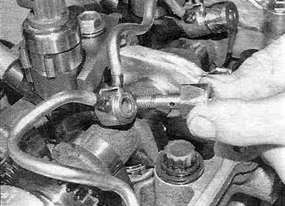
Figure 11.13,a. Unscrew the four hollow bolts...
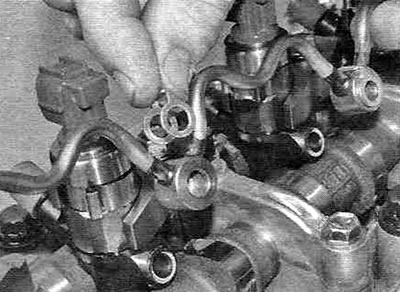
Figure 11.13, b.... remove the return fuel line and remove the double sealing washers.
14. Mark the position of the injectors to ensure that they are installed exactly the same during assembly, as the engine control unit uses this information when injecting fuel.
15. Unscrew and remove the injector mounting bolts together with the clamping strips and washers. Note that the convex side of the washer should be flush with the top of the clamping plate (see figure 11.15, a, b).
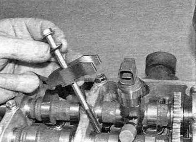
Figure 11.15,a. Loosen the mounting bolt and remove it together with the injector pressure plate.
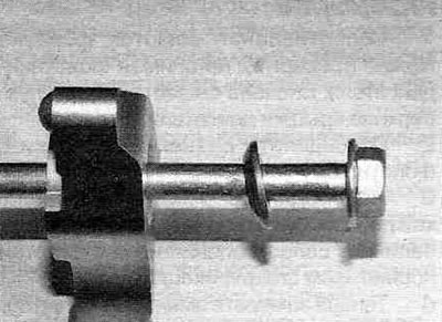
Figure 11.15,b. The convex side of the washer should be adjacent to the pressure plate.
16. Using a screwdriver or other suitable lever, remove the injectors from the cylinder head, marking their position. Place the injectors and their mounting elements in separate plastic bags (see Figure 11.16, a-g).
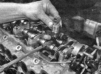
Figure 11.16,a. To remove the injector, use a suitable lever...
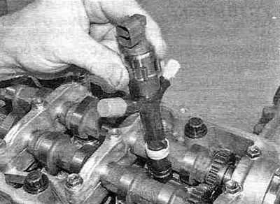
Figure 11.16, b....and remove it from the cylinder head.
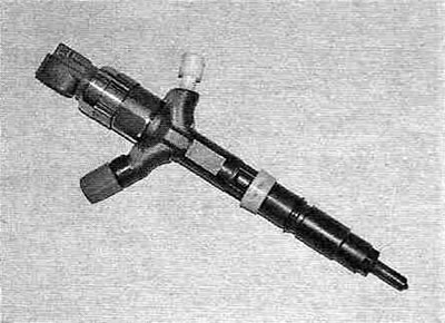
Figure 11.16, c. This is what the injector looks like after being removed from the cylinder head.
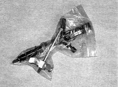
Figure 11.16, d. Place the injectors together with the mounting parts in separate plastic bags.
17. Remove the O-rings and top seals from the injectors.
18. Remove the injector seats from the cylinder head.
Installation
19. Before installing the injectors, thoroughly wipe the cylinder head, injectors, return fuel line and high-pressure fuel lines.
20. Place the new injector seats into the cylinder block. To accurately install the saddles in their places, use a narrow screwdriver (see Figure 11.20).
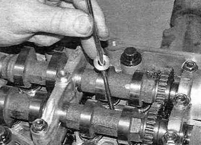
Figure 11.20. Use a narrow screwdriver to install the injector seats into the cylinder head.
21. Install the spring clips onto the injectors so that their slots are located above the mounting protrusions of the injectors. Install new O-rings and top seals, lubricate O-rings with clean engine oil.
22. Align the injector mounting protrusion with the groove in the cylinder head and install the injector in its place (see Figure 11.22).
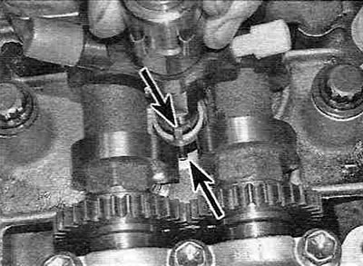
Figure 11.22. Align the injector mounting protrusion with the groove in the cylinder head and install the injector in its place. Make sure that the cutout on the spring clip is over the mounting lug on the injector.
If the injector does not install due to the O-ring being in the way, remove the injector completely and reinstall it.
Warning. Make sure that each injector is installed in its own cylinder, in accordance with the markings applied during removal.
23. Install the remaining injectors in the same order, then, lightly lubricate the lower part of the mounting bolt heads, install them together with the clamping strips and washers. The washers must be placed on the bolts with the convex side facing the pressure plate.
24. Tighten the injector mounting bolts by hand, then tighten to the specified torque.
25. Install the fuel return line with the new double sealing washers, with the washers facing forward. Lubricate the bottoms of the four hollow bolt heads with clean engine oil, then install them and tighten them to the specified torque.
Note: If the hollow bolts are overtightened, the fuel return line (tube) will have to be replaced.
26. Connect the fuel return line with a new double sealing washer to the timing belt side of the cylinder head. Lubricate the underside of the union nut head with clean engine oil, then install and tighten to the specified torque.
27. At this point, Toyota recommends performing a leak test on the fuel return line, but after this test, the check valve will have to be replaced.
- Begin the inspection by disconnecting the flexible hose from the fuel return line check valve outlet pipe, located on the timing belt side of the cylinder head. Using a hex key, unscrew the check valve plug. Remove the spring and ball from the valve, then replace the plug and tighten it. Connect a pump with a pressure gauge to the outlet pipe of the check valve and create a pressure of 7 bar for 10 minutes.
- Apply soapy water to all fuel return line connections and watch for soap bubbles. If they appear anywhere, remove the fuel line, replace the corresponding double sealing washers, then reinstall the fuel line and check its tightness again.
- After making sure the connections are tight, unscrew the check valve and remove the outlet pipe from it, then screw in a new check valve and connect the pipe, after replacing the double sealing washers. Tighten the check valve and its plug to the specified torques. Connect the flexible hose to the outlet pipe of the check valve.
28. Install the valve cover as described in chapter 2B.
29. Install the lower clamps for fastening the fuel injector feed pipes to the intake manifold housing.
30. Install the high-pressure fuel lines as described in paragraph 10.
(The official source is on the portal: toyotaman.ru)
31. Install the engine wiring harness in its place and connect the injector wiring connectors.
32. Install the coolant expansion tank and tighten the mounting bolt.
33. Start the engine and check for fuel leaks.