



Camshafts and valve lifters
Note: Always check camshaft end play before removal and inspect thoroughly before installation.
Removal
1. Disconnect the negative battery terminal.
2. Remove the valve cover (see paragraph 4).
3. Referring to paragraph 3, set the piston of cylinder No. 1 to TDC of the compression stroke. Visually check that the mark on the crankshaft pulley/damper is aligned with the "0" mark on the timing chain cover and that the TDC marks on the camshaft sprockets are in line with the marks on the camshaft bearings (see Figure 3.8 and 6.7).
4. After setting the piston of cylinder No. 1 to TDC of the compression stroke, apply paint marks to those chain links that coincide with the "upper" timing marks on the camshaft sprockets (see figure 7.4).
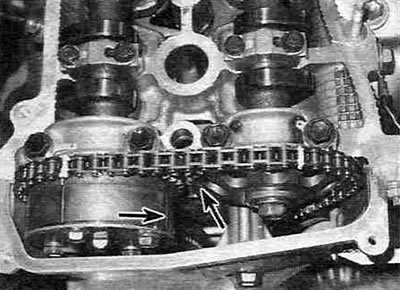
Figure 7.4. When the TDC marks on the sprockets and bearing caps are aligned, apply timing marks to the chain with paint opposite the marks on the sprockets.
Note: There are two types of marks on the camshaft sprockets: "lower" marks for alignment when setting TDC (and only for this) and two other "upper" marks used to align with the marks on the timing chain during assembly.
5. While holding the camshaft with an open-end wrench from turning, loosen the sprocket mounting bolts by a few turns (see Figure 6.19). If the camshaft sprockets have changed position while loosening the bolts, turn the crankshaft clockwise until the marks align.
6. Remove the tensioner from the timing chain cover (see figure 6.13,a,b) and the camshaft position sensor from the cylinder head (see chapter 6A).
7. Loosen the camshaft sprocket mounting bolts. Remove the timing chain from the sprockets and remove the sprockets from the camshafts. Make sure the variable valve timing actuator is installed on the intake (rear) camshaft. After removing the sprockets, tie the timing chain to the engine shield with pieces of wire (see figure 7.7) - this will prevent it from falling into the engine during the remaining stages of the procedure.
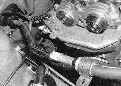
Figure 7.7. Once the camshaft sprockets are removed, tie the timing chain with a piece of wire.
Also place rags in the open space of the timing chain cover to prevent dirt and foreign objects from getting into the engine.
8. Check the markings on the camshaft support caps. Each cover must be marked with a serial number from 1 to 5, the letter I (inlet) or E (outlet) and an arrow indicating the direction of installation (see Figure 7.8).
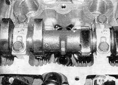
Figure 7.8. The camshaft support caps are numbered and have arrows on them that should point towards the timing chain.
9. Loosen the camshaft bearing cap mounting bolts in two or three passes, in the sequence, reverse in relation to the sequence of their tightening (see Figure 7.22).
Warning. Don't mix up the lids. During assembly, each cover must be installed strictly in its place.
10. Remove the bearing caps, then remove the camshaft (camshafts) from the cylinder head. Mark the intake and exhaust camshafts to avoid confusion during assembly.
Note: When looking at the engine from the front of the car, the front (closest to you) the camshaft closest to the firewall will be the exhaust camshaft, and the one closest to the firewall will be the intake camshaft. During assembly, it's crucial that the camshafts are installed in their original positions.
11. Remove the valve lifters from the cylinder head and stack them in order of matching the valves and cylinders (see figure 7.11, a, b).
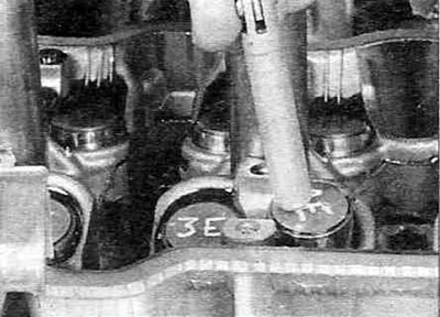
Figure 7.11,a. Mark the valve lifters (I - intake, E - exhaust) and number them according to their location, then remove them from the head using a magnet.
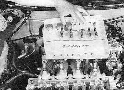
Figure 7.11,b. Label the storage box for the valve lifters and camshaft bearing caps in the appropriate order.
Warning. Don't mix up the pushers. During assembly, each pusher must be installed strictly in its place.
12. Check the camshafts, bearing shells and valve lifters as described below. Also check for wear on the camshaft sprocket teeth. Inspect the chains for cracks and excessive wear on the chain rollers, and check the chain stretch (see paragraph 6). Worn components are subject to replacement.
Examination
13. Before removing the camshafts, check their axial clearance with a dial indicator, as shown in the figure 7.13.
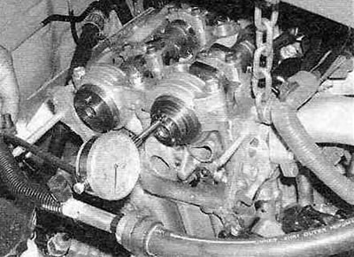
Figure 7.13. To measure the camshaft end play, install a dial indicator as shown and move the camshaft forward as far as it will go, then back it off and record the indicator reading.
Move the camshaft back as far as it will go and reset the indicator readings, then push the camshaft forward as far as possible and check the indicator readings - this will be the value of the axial clearance. If the intake camshaft axial clearance is greater than that specified in the Specifications, check the wear of the journal bearing No. 1. If the wear is severe, the bearing must be replaced. If the exhaust camshaft axial clearance exceeds the value specified in the Specifications, the camshaft itself and/or the cylinder head must be replaced.
14. After removing the camshafts, visually inspect the condition of the working surfaces of the camshaft bearings in the cylinder head and ensure there are no scoring, surface cavities, metal abrasion or uneven wear. If the above damage is present on the working surfaces of the bearings, the cylinder head or bearing liners of bearing No. 1 of the intake camshaft must be replaced (see figure 7.14,a,b).
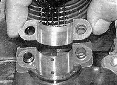
Figure 7.14,a. Check the working surfaces of the camshaft bearings and their covers No. 2 through No. 5 for the absence of pits, scoring, and abnormal wear.
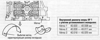
Figure 7.14, b. If the bearing liners of support No. 1 are worn or damaged, they must be replaced.
15. Measure the outside diameter of each camshaft journal with a micrometer and record the measurement results (see Figure 7.15).
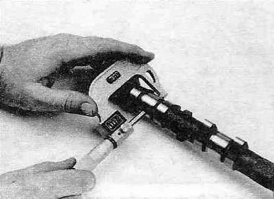
Figure 7.15. Use a micrometer to measure the diameter of each bearing journal on both camshafts.
Compare them with the data Specifications. Measure the inner diameter of the corresponding camshaft bearings and record the measurement results. Subtracting the journal outer diameter from the corresponding camshaft bearing inner diameter will give you the journal-to-bearing oil clearance. Compare these results with the data Specifications. If at least one of the obtained results is outside the limits specified in Specifications, the corresponding camshaft and/or cylinder head must be replaced.
16. Measure the height of each camshaft lobe with a micrometer (see Figure 7.16).
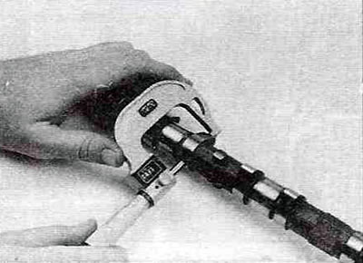
Figure 7.16. Measure the height of each cam lobe on both camshafts with a micrometer.
Compare the results with the data Specifications. If the height of at least one cam does not correspond to the minimum permissible Specifications, replace the camshaft (camshafts).
17. Check the radial runout of the camshafts. Install the camshaft back into the cylinder head and connect a dial indicator to the center journal. Reset the indicator to zero. While slowly turning the camshaft, read the indicator readings. If the measurement results exceed the established Specifications size, replace the camshaft.
18. Inspect each tappet for burrs and scratches (see Figure 7.18).
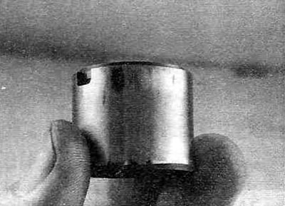
Figure 7.18. Wipe off the oil and inspect the condition of each tappet for signs of wear and scoring.
19. Measure the outside diameter of each tappet with a micrometer (see Figure 7.19) and the internal diameter of the corresponding pilot hole.
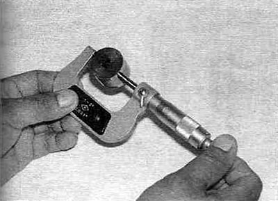
Figure 7.19. Measure the outside diameter of each lifter and the inside diameter of the pilot hole to determine the valve lifter oil clearances.
Subtracting the tappet diameter from the pilot hole diameter will give you the valve tappet oil clearance. Compare the calculation results with the data Specifications. If the size of at least one gap exceeds the maximum permissible Specifications, the tappets and/or cylinder head must be replaced.
Installation
20. If the bearing liners No. 1 of the intake camshaft were replaced or removed, install them into the cylinder head and bearing cover (see figure 7.20,a,b).
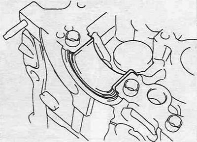
Figure 7.20,a. Install the combined bearing insert No. 1 of the intake camshaft into the bearing...
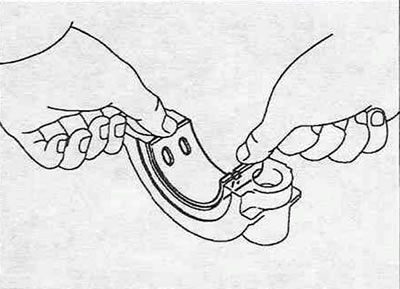
Figure 7.20, b...and the upper insert - into the cover of support No. 1 of the intake camshaft.
Apply molybdenum-based assembly gel to the camshaft lobes and journals and install them into the cylinder head so that the camshaft lobes of cylinder #1 are facing away from each other and their dowel pins are facing up (see Figure 7.20,c).
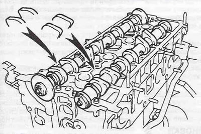
Figure 7.20, c. Install the camshafts in the cylinder head so that the camshaft lobes of cylinder No. 1 are directed in different directions relative to each other, at an angle of approximately 30° to the vertical.
If you are installing old camshafts, make sure that you do not mix them up during installation.
21. Install the support caps and tighten the mounting bolts, then tighten them by hand.
22. Tighten the support cover mounting bolts to the specified torque Specifications moment in several equal passes, guided by the figure shown 7.22 tightening sequence.
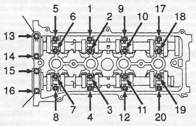
Figure 7.22. Sequence of tightening the bolts for fastening the camshaft support covers.
23. Place the timing chain on the camshaft sprockets so that the marks painted on the chain links during removal align with the "upper" timing marks on the sprockets, then install the sprockets together with the chain on the camshafts, aligning the corresponding holes on the sprockets with the mounting pins on the camshaft hubs. Install the sprocket mounting bolts and tighten them by hand. At this point, the mark on the crankshaft pulley should be aligned with the "0" mark on the timing chain cover, the TDC marks on the bearing caps should be in line with the "upper" TDC marks on the camshaft sprockets and the marked chain links, and the timing ("lower") marks on the sprockets should be parallel to the top edge of the timing chain cover. All slack in the timing chain should be on the tensioner side (see figure 7.4).
24. Once again, make sure that the sprockets are installed on the correct camshafts and tighten the mounting bolts to the specified torque.
25. Install the timing chain tensioner as described in steps 34 and 35 paragraph 6.
26. Installation of the remaining components is carried out in the reverse order of removal.