



Cylinder head
Note: Allow the engine to cool completely before starting the procedure.
Removal
1. Relieve the pressure in the fuel system (see chapter 4A), then disconnect the cable from the negative battery terminal.
2. Drain the coolant (see Chapter 1A).
3. Remove the alternator drive belt and alternator (see chapter 5).
4. Remove the valve cover (see paragraph 4).
5. Remove the throttle body, injectors and fuel rail (see chapter 4A).
6. Remove the intake manifold (see paragraph 8).
7. Remove the exhaust manifold (see paragraph 9).
8. Remove the timing chain and camshaft sprockets (see paragraph 6).
9. Remove the camshafts and valve lifters (see paragraph 7).
10. Remove the valve timing control valve (see figure 5,a).
11. Label and disconnect the coolant hoses and wiring connectors from the cylinder head (see Figure 10.11).
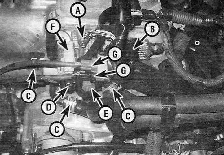
Figure 10.11. Disconnect the following components from the driver's side cylinder head and position the wiring harness aside:
A - Ground wire;
B - Camshaft position sensor;
C - Cooling system hoses;
D - Oil pressure sensor;
E - Coolant temperature sensor;
F - Interference suppressor;
G - Oxygen sensor connector.
12. Using a 10 mm hex head-and-crank bit, loosen the cylinder head mounting bolts, making 1/4 turn in one pass, until they will not turn away with the force of your hand. Loosen the bolts in the reverse order to that shown in the figure 10.24, to prevent distortion of the mating surface and the appearance of cracks on the head body.
13. Carefully, lifting straight up, remove the head from the cylinder block. If the head is stuck to the block, very carefully pry it up using the specially provided protruding lugs on the transmission side, being careful not to damage the mating surfaces of the head and block (see Figure 10.13).
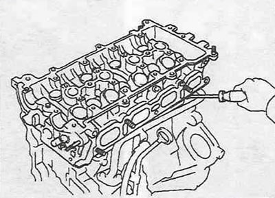
Figure 10.13. If the head is stuck to the block, carefully push it away from the block using the protruding lugs on the transmission side.
14. Remove all remaining external parts, preparing the head for thorough cleaning and inspection.
Installation
15. Before installing the head, thoroughly clean the block and head connector surfaces.
16. Using a soft scraper, remove traces of the old gasket and carbon deposits (see Figure 10.16), then wipe the mating surfaces with a rag soaked in varnish thinner or acetone.
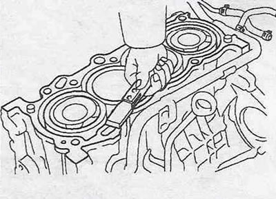
Figure 10.16. Carefully remove any remaining old gasket and sealant from the mating surfaces of the cylinder head and block.
If oil remains on the mating surfaces after the head is installed, this will lead to uneven compression of the gasket and cause leaks and burnouts. When working with the block, line the cylinders with a clean rag to prevent debris from getting into them. To clean the cylinders and channels of the block, use compressed air or a vacuum cleaner.
17. Inspect the head and block connector surfaces for nicks, deep scratches, and other damage. If the damage is minor, it can be removed with a file. Serious damage can only be repaired in a specialized workshop by grinding.
18. Using a tap of the appropriate size, tap the threads in the holes for the mounting bolts in the cylinder head, then clean the holes with compressed air or a vacuum cleaner.
Caution! When working with compressed air, wear a protective mask or goggles.
19. Using a wire brush, clean the threads of the mounting bolts from rust. Dirt, rust, sealant and damaged threads can cause incorrect tightening torque.
20. Reinstall all parts that were removed from the cylinder head.
21. Place the new gasket, aligning the corresponding holes with the mounting pins on the block surface (see Figure 10.21,a), then apply RTV sealant to the corners of the gasket as shown in the picture 10.21,b.
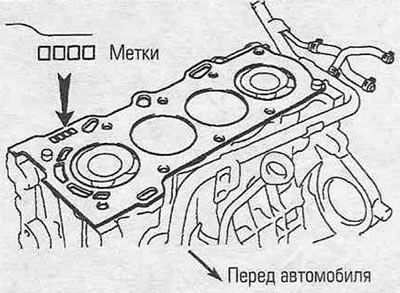
Figure 10.21,a. Place the gasket on the cylinder block, aligning it with the guide pins, with the marks facing outward.
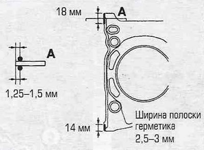
Figure 10.21,b. Apply RTV sealant to the cylinder head gasket areas as shown.
22. Being careful not to move the gasket, carefully install the head onto the cylinder block.
23. Before tightening, lubricate the threaded parts of the head bolts with a thin layer of engine oil.
24. Install the bolts in their places and tighten them by hand. Tighten the head bolts to the specified torque, strictly following the recommended tightening sequence (see Figure 10.24).
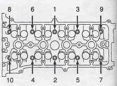
Figure 10.24. Cylinder head bolt tightening sequence.
25. Installation of the remaining components is the reverse procedure.
26. Check and adjust, if necessary, the clearances in the valve drive mechanism (see Chapter 1A).
27. Change the engine oil and oil filter (see Chapter 1A).
28. Fill the cooling system (see Chapter 1A), start the engine and check for leaks.
[The article is taken from a web resource ToyotaMan.ru]