



Timing Chain and Sprockets
Caution: The engine must be completely cool before starting this procedure.
Note: This procedure requires special tools. Before starting work, read the description of the procedure and prepare all necessary tools and equipment.
Removal
1. Disconnect the ground cable from the negative battery terminal.
(The material was taken from a resource: «toyotaman.ru»)
2. Remove the alternator drive belt (see Chapter 1A) and generator (see chapter 5).
3. Remove the valve cover (see paragraph 4) and the ABS system hydraulic modulator, if any (see chapter 9).
4. Apply the handbrake and chock the rear wheels. Loosen the lug nuts on the right front wheel, then raise the front of the vehicle and support it on jack stands. Remove the right front wheel and the mudguard from the right front wheel arch.
5. Drain the coolant (see Chapter 1A).
6. While the coolant is draining, contact chapter 10 and remove the power steering pump without disconnecting the lines. Tie the pump to the body with a piece of wire so that it does not interfere with the work.
7. Set the piston of cylinder No. 1 to TDC of the compression stroke (see paragraph 3). Visually ensure that the piston of cylinder No. 1 is at TDC of the compression stroke by checking the alignment of the marks on the crankshaft pulley/damper and the "0" mark on the timing chain cover and the alignment of the marks on the camshaft sprockets and bearing caps (see Figure 6.7).
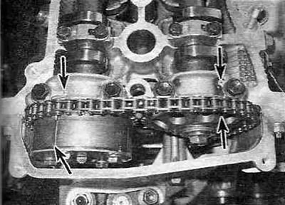
Figure 6.7. Make sure that piston No. 1 is at TDC by checking the alignment of the marks on the camshaft sprockets (shown by the lower arrows) with marks on the camshaft bearing caps (shown by the upper arrows).
Note: There are two types of marks on the camshaft sprockets: marks for alignment when setting TDC (and only for this) and two other marks used to align with the marks on the timing chain during assembly.
8. Remove the crankshaft pulley/damper without allowing the crankshaft to turn, so as not to disturb the TDC setting (see paragraph 11). If the crankshaft has rotated and the TDC setting has been lost, piston #1 must be reset to TDC. Piston #1 of cylinder #1 must remain at TDC on the compression stroke throughout the entire procedure.
9. Support the engine with a hoist or a trolley jack. Place a piece of board between the jack head and the oil pan to prevent damage to the pan (see figure 6.9).
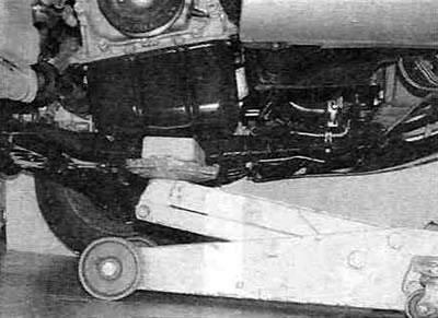
Figure 6.9 If a lifting mechanism is not available, the engine can be supported from underneath using a hydraulic trolley jack with a wooden shim.
10. Remove the engine mount from the passenger side (see paragraph 17).
11. Remove the accessory drive belt tensioner and crankshaft position sensor from the timing chain cover (see Figure 6.11).
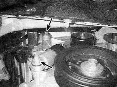
Figure 6.11. Drive belt tensioner mounting bolts.
Also unscrew the bolt securing the crankshaft position sensor wiring and move the harness to the side.
12. Remove the engine oil pan (see paragraph 13).
13. Disconnect the main wiring harness assembly and remove the timing chain tensioner from the rear of the timing chain cover (see figure 6.13,a,b).
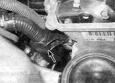
Figure 6.13,a. Remove the two bolts securing the main wiring harness to the timing chain cover and move the harness to the side.
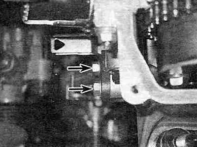
Figure 6.13,b. Timing chain tensioner mounting nuts (shown by arrows).
14. Loosen the mounting bolts and remove the timing chain cover (see Figure 14, a-g).
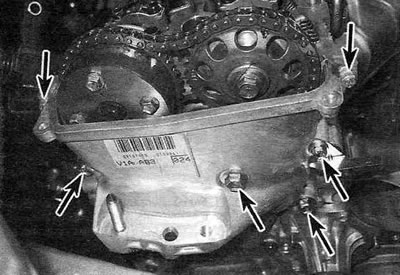
Figure 6.14,a. Upper timing chain cover mounting bolts.
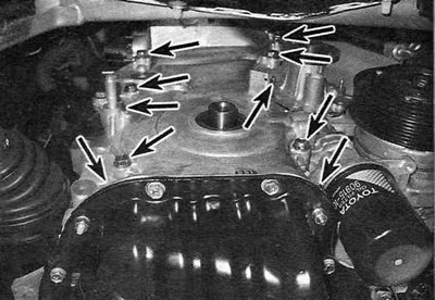
Figure 6.14,b. Lower timing chain cover mounting bolts - if you plan to reinstall these, record the thread size, location, and length of each bolt when removing them to make reassembly easier.
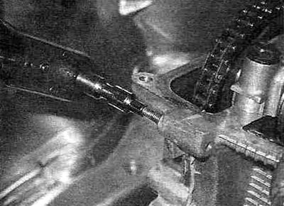
Figure 6.14, c. It is necessary to unscrew the timing chain cover mounting studs...
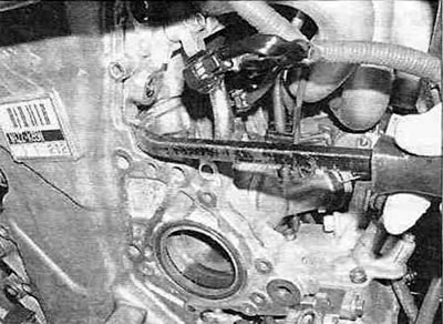
Figure 6.14, g...before removing the cover from the engine.
15. Remove the crankshaft position sensor timing disk from the crankshaft (see Figure 6.15).
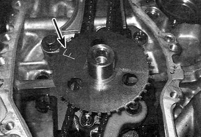
Figure 6.15. Remove the crankshaft position sensor timing disc - remember that the F mark (shown by the arrow) must be on the outside during assembly.
16. Remove the timing chain tensioner shoe and lower guide (see Figure 6.16).
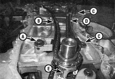
Figure 6.16. Timing chain tensioner shoe fastening parts:
A - Axle bolt;
B - Timing chain tensioner shoe;
C - Fixed damper mounting bolts;
D - Fixed timing chain guide;
E - Lower timing chain guide.
17. Lift the timing chain, remove it from the camshaft sprockets and then remove it from the engine together with the crankshaft sprocket. The crankshaft sprocket should be easily removed by hand. If it won't come off, use a pair of flat-head screwdrivers to pry it off. Smoothly and evenly press the sprocket off the crankshaft.
Note: If you plan to use the old chain after removal, mark the outside of it with paint or chalk. Incorrect installation of the chain will cause noise and accelerated wear.
18. Remove the fixed timing chain guide (see Figure 6.16).
19. To remove the camshaft sprockets, loosen their mounting bolts while holding the camshaft from turning with an open-end wrench (see Figure 6.19).
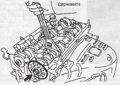
Figure 6.19. When removing the sprocket, hold the camshaft from turning with an open-end wrench. When removing the intake camshaft sprocket, loosen and unscrew only central mounting bolt.
Having remembered the position of the timing marks on the camshaft sprockets, unscrew the bolts. Remove the sprockets from the locating pins. If they cannot be removed by hand, use a small puller, inserting its paws into the holes in the sprockets.
Note: These models use a variable valve timing system in which the actuator is connected to the intake camshaft sprocket. To remove the intake camshaft sprocket on these models, only the central mounting bolt must be loosened and unscrewed. Do not touch the four actuator mounting bolts on the outer edge of the sprocket.
Examination
20. Visually inspect all components for signs of wear or damage. Inspect the timing chain for loose rivets, cracks, worn rollers and side plates. Inspect the camshaft sprockets and ensure there are no bent, chipped or broken teeth. Also check the timing chain stretch and sprocket wear as shown in the figure 6.20,a,b.
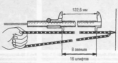
Figure 6.20,a. Timing chain stretch is determined by measuring the length of a section of the chain corresponding to 8 links (16 pins), in three or more randomly selected locations. If the amount of stretching in at least one area exceeds the permissible limit Specifications, the chain must be replaced.
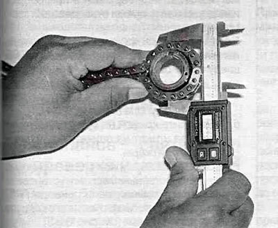
Day. 6.20,b. Wrap the timing chain around each sprocket and measure the sprocket diameter by placing the jaws of the calipers on the chain rollers.
For greater reliability, make changes in several places. The measurement results must comply with the standards Specifications, otherwise the corresponding component must be replaced. If the vehicle has a high mileage or the engine is performing poorly, it makes sense to replace the timing chain and its sprockets as a set.
21. Check the wear of the tensioner shoe and timing chain guides (see Figure 6.21).
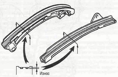
Figure 6.21. Timing chain guide wear is determined by the distance between the top of the contact surface and the bottom of the wear groove.
If wear exceeds the permissible limit Specifications, replace the dampers. Please note that small nicks in the guide shoes are acceptable. If the timing chain shoe and guides are excessively worn, it is necessary to check the oil jet at the front of the block, through which oil is supplied to the timing chain and oil pump, to the timing chain shoe and guides for lubrication. If the hole is clogged, clean it out (see Figure 14.5,g).
22. Remove all traces of old sealant and thoroughly clean the mating surfaces of the timing chain cover, as well as the cylinder head and block.
23. Make sure that the position of the dowel pins on both camshafts is at 12 o'clock on the dial, then install both sprockets in their places, aligning the dowel holes on the sprockets with the dowel pins on the camshafts. Lubricate the threaded portions of the mounting bolts with a suitable locking compound and ensure that the washers are in place. Holding the camshaft from turning as described in paragraph. 19, tighten the mounting bolts to the specified torque (see Specifications).
24. Turn the camshafts as far as necessary to align the TDC marks on the sprockets (see Figure 6.7).
25. If the crankshaft has been turned and the TDC marks do not match, it should be turned so that the keyway on the pulley is at the 12 o'clock position on the dial and is in line with the geometric axis of the cylinders.
26. Install the fixed timing chain guide (see Figure 6.16).
27. Place the timing chain on the crankshaft sprocket and align painted link No. 1 with the mark on the sprocket. Install the chain together with the sprocket on the crankshaft, then install the lower timing chain guide (see Figure 6.27).
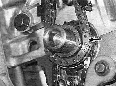
Figure 6.27. Wrap the timing chain around the crankshaft sprocket, aligning painted link No. 1 with the mark on the sprocket, install the sprocket together with the chain on the crankshaft, then install the lower chain guide.
Note: There are three painted links on the timing chain. Link #1 is located at a distance from the other two colored links, which are close to each other.
28. Pull the chain along the fixed guide and place it on the exhaust camshaft sprocket, then on the intake camshaft sprocket. The two remaining painted chain links should align with the marks on the camshaft sprockets (see Figure 6.28).
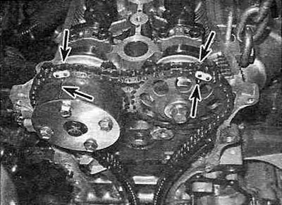
Figure 6.28. Place the timing chain on the exhaust and intake camshaft sprockets and align the remaining two painted links with the marks on the sprockets.
Make sure there is no slack on the right side of the chain.
29. While tensioning the left side of the chain with one hand, install the timing chain tensioner shoe. Tighten the axle bolt to the specified torque. After assembly, make sure that the mounting lug on the tensioner shoe cannot pass the stop on the cylinder head (see Figure 6.29).
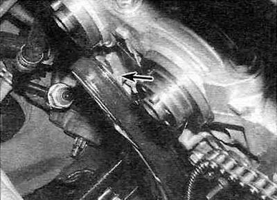
Figure 6.29. After installing the tensioner shoe, make sure that the mounting lug on the shoe (shown by the arrow) cannot pass the stop on the cylinder head.
30. Once again, make sure that the piston of cylinder No. 1 is at TDC of the compression stroke, and the valve timing marks on the camshaft and crankshaft sprockets are aligned with the painted links of the timing chain.
31. Install the crankshaft position sensor timing disk in its place, with the F mark facing outward.
32. Apply a bead of RTV sealant to the mating surface of the timing chain cover (see figure 6.32,a,b).
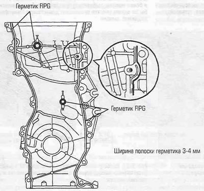
Figure 6.32,a. Diagram of applying sealant to the timing chain cover.
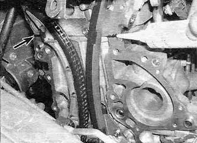
Figure 6.32,b. Also apply sealant to the parting line between the head and the cylinder block on each side.
Place the cover on the engine and tighten the mounting bolts.
33. Tighten the bolts evenly to the specified torque in several equal passes. Follow the sealant manufacturer's recommendations during assembly and allow for the sealant's curing time.
34. Wind up and lock the timing chain tensioner in the "zero" position as follows:
- Raise the ratchet cam and push the plunger into the tensioner housing until it stops (see Figure 6.34).

Figure 6.34. Raise the ratchet cam and push the plunger into the housing until the hook on the tensioner housing can be hooked onto the pin on the plunger.
- Hook the hook on the tensioner body onto the pin on the plunger to secure the plunger.
35. Lightly lubricate the tensioner sealing ring with engine oil and install the tensioner into the timing chain cover so that the hook on its housing is facing upwards (see Figure 6.35).
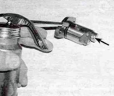
Figure 6.35. Lubricate the tensioner sealing ring with engine oil and install the tensioner into the timing chain cover so that the hook on its housing is pointing upward.
36. Install the crankshaft pulley/damper (see paragraph 11).
37. Turn the engine crankshaft slightly counterclockwise to tighten the chain (see Figure 6.37).
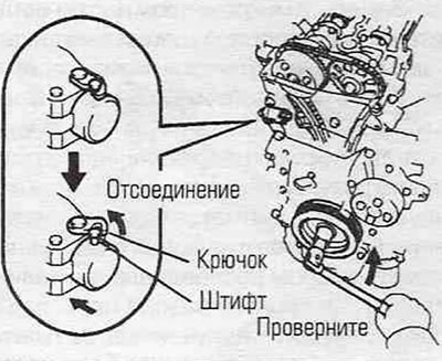
Figure 6.37. Turn the engine crankshaft counterclockwise until the hook on the tensioner housing disengages from the plunger pin.
When turning, the hook on the tensioner body should disengage from the pin on the plunger, and the plunger, under the spring pressure, should pop out of the tensioner body and tighten the timing chain. If the plunger doesn't pop out, press down on the tensioner shoe and disengage the hook on the tensioner body with a screwdriver.
38. Turn the engine crankshaft several revolutions clockwise and set the piston of cylinder No. 1 to TDC of the compression stroke (see paragraph 3). Visually check that the mark on the crankshaft pulley/damper aligns with the "0" mark on the timing chain cover and that the timing marks on the camshaft sprockets are in line with the marks on the camshaft bearings (see Figure 6.7).
39. Installation of the remaining components is carried out in the reverse order of removal.