
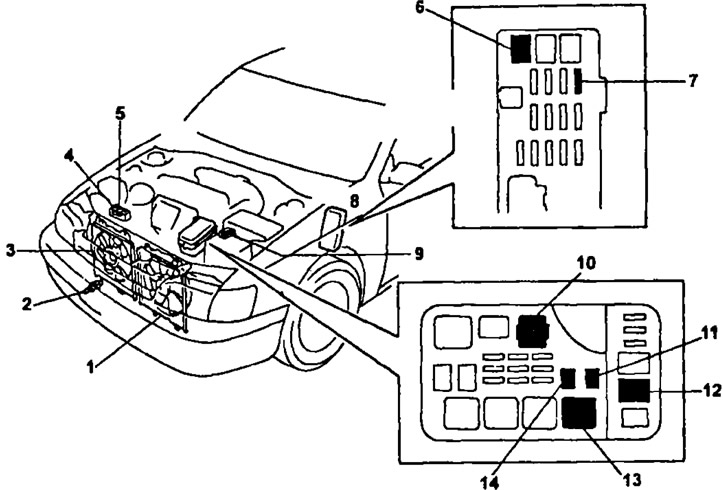
The layout of the elements of the electric fan control system on the car (4A-FE, 7A-FE): 1 - electric fan of the cooling system, 2 - sensor-switch for coolant temperature, 3 - main fuse "MAIN" FL (2,0 L), 4 - relay and fuse box No. 1 (№1 JB), 5 - relay and fuse box No. 2 (№2 JB), 6 - location of block No. 1, 7 - control fuse "GAUGE" (10 A), 8 - cooling fan relay N91, 9 - location of block No. 2 on the car, 10 - fuse "AM2" (30 A), 11—main engine relay "MAIN", 12 - fusible insert "RDI" (30 A).
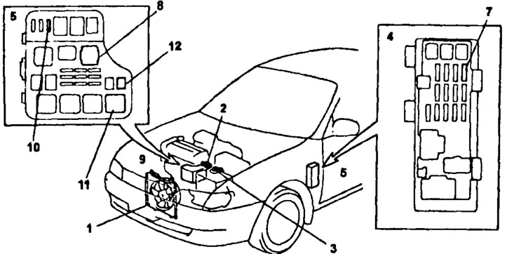
The layout of the elements of the electric fan control system on the car (3S-FE, 4S-FE): 1 - N91 electric fan, 2 - coolant temperature switch sensor, 3 - electric fan No. 1, 4 - electric fan relay No. 2 (models with air conditioning), 5 - relay No. 3 electric fan (models with air conditioning), 6 - fuse "AM" 40 A, 7 - fuse "GAUSE" 10 A, 8 - fuse box, 9 - main fuse "MAIN" 10 A, 10 - relay No. 1 electric fan, 11 - fuse "RDI" 30 A, 12 - fuse "ALT 100 A", 13 - main engine relay.
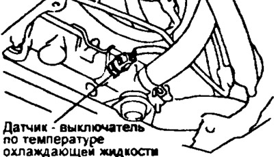
Coolant temperature switch
Note: (4A-FE, 7A-FE) the sensor-switch for the temperature of the coolant is located in the inlet pipe.
1. Drain the coolant and remove the coolant temperature switch.
3S-FE, 4S-FE | 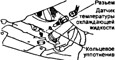
2C-T |
2. Check the sensor-switch for coolant temperature,
- A) Using an ohmmeter, check that there is no continuity between the sensor-switch leads when the coolant temperature is above 93°C.
- b) Using an ohmmeter, check for continuity between the terminals of the sensor - switch at a coolant temperature of not more than 83°C.
3. Establish the gauge - the switch on temperature of a cooling liquid.
4. Fill in coolant.
Checking the main engine relay ("ENGINE MAIN")
The relay is in the relay box and fuse pin #2 (in the engine compartment).
Attention: the layout of the pins of the main relay connector may be different on different models, when checking, pay attention to the pin numbers.
1. Remove the relay box cover and main relay.
3S-GE, 4A-FE, 5E-FE, 7A-FE
2. Check relay circuits. using an ohmmeter:
- A) Check for continuity between leads "1 and "3", "2" And "4".
- b) Make sure there is no continuity between the terminals "4" And "5".
If these conditions are not met, replace the relay.
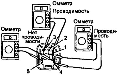
3 Check the operation of the relay using an ohmmeter and a battery:
- A) Apply voltage to terminals "1" And "3".
- b) Use an ohmmeter to check for continuity between the terminals "4" And "5".
- V) Use an ohmmeter to check for continuity (chain break) between pins "2" And "4".
If these conditions are not met, replace the relay.
2C, 2C-T, 3S-FE, 4S-FE
2. Check the electrical circuits of the relay using an ohmmeter:
- A) Check continuity between leads with an ohmmeter "3" And "5", "2" And "4".
- b) Check with an ohmmeter that there is no continuity between the terminals "1" And "2".
If these conditions are not met, replace the relay.
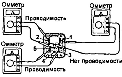
3. Check the operation of the relay using an ohmmeter and a battery:
- A) Apply voltage to terminals "5" And "3".
- b) Use an ohmmeter to check for continuity between the terminals "1" And "2".
- V) Use an ohmmeter to check for continuity (chain break) between pins "2" And "4".
If these conditions are not met, replace the relay.
All engines
4. Replace the relay and block cover.
Relay No. 1 electric fan
The relay is located in the relay and fuse box No. 2 (in the engine compartment).
Attention! the pinout of the relay connector may be different on different models, when checking, pay attention to the pin numbers.
1. Remove the cooling fan relay.
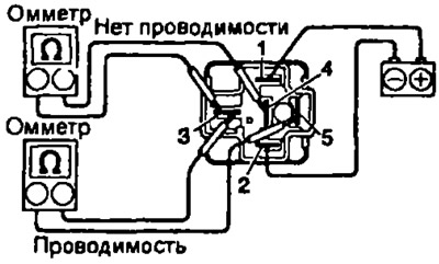
2C, 3S-FE, 3S-GE, 4A-FE, 4S-FE SE-FE, 7A-FE
2. Check the electrical targets of the relay: using an ohmmeter, check for continuity between the terminals "1" And "2", "3" And "4".
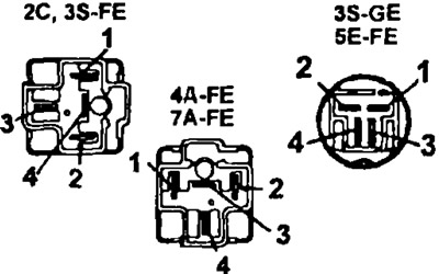
If these conditions are not met, replace the relay.
3. Check the operation of the relay: using an ohmmeter and a battery, apply voltage to the terminals "1" And "2" relay connector and check for continuity (chain break) between pins "3" And "4".
If this condition is not met, replace the relay.
2S-T
3. Check the electric fan relay,
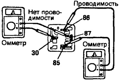
- A) Check continuity between leads with an ohmmeter "86" And "85", And "30" And "87a".
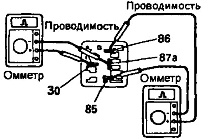
- b) Apply battery voltage to the relay outputs "86* and "85".
- V) Check with an ohmmeter that there is no continuity between the relay terminals "30" And "87a".
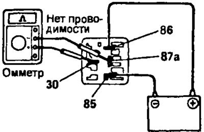
If these conditions are not met, replace the relay.
All engines
4. Install relay and block cover.
Relay No. 2 electric fan (2S-T, 3S-FE, 4S-FE)
1. Remove the cover of the relay box and relay No. 2 of the electric fan.
2. Check the electric fan relay,
- A) Check continuity between leads with an ohmmeter "1" And "2", And "3" And "4".
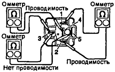
- b) Check with an ohmmeter that there is no continuity between the terminals "3" And "5".
- V) Apply battery voltage to the relay outputs "1" And "2".
- G) Check with an ohmmeter that there is no continuity between the relay terminals "3" And "4".
- d) Check continuity between leads with an ohmmeter "3" And "5".
If these conditions are not met, replace the relay.
3. Install fan relay #2 and relay box cover.
Relay No. 3 electric fan (2S-T, 3S-FE, 4S-FE)
1. Remove the cover of the relay box and relay No. 3 of the electric fan.
2. (3S-FE, 4S-FE) Check the blower relay.
- A) Check continuity between leads with an ohmmeter "1" And "2".
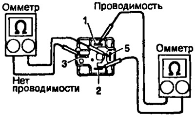
If these conditions are not met, replace the relay.
- b) Apply battery voltage to the relay outputs "1" And "2".
- V) Check continuity between leads with an ohmmeter "3" And "5".
If these conditions are not met, replace the relay.
3. (2S-T) Check the blower relay.
- V) Check continuity between leads with an ohmmeter "86" And "86".
- b) Check with an ohmmeter that there is no continuity between the terminals "30" And "87". If these conditions are not met, replace the relay.
- V) Apply battery voltage to the relay outputs "86" And "85".
- G) Check continuity between leads with an ohmmeter "30" And "87". If these conditions are not met, replace the relay.
4. Install fan relay #3 and relay box cover.