
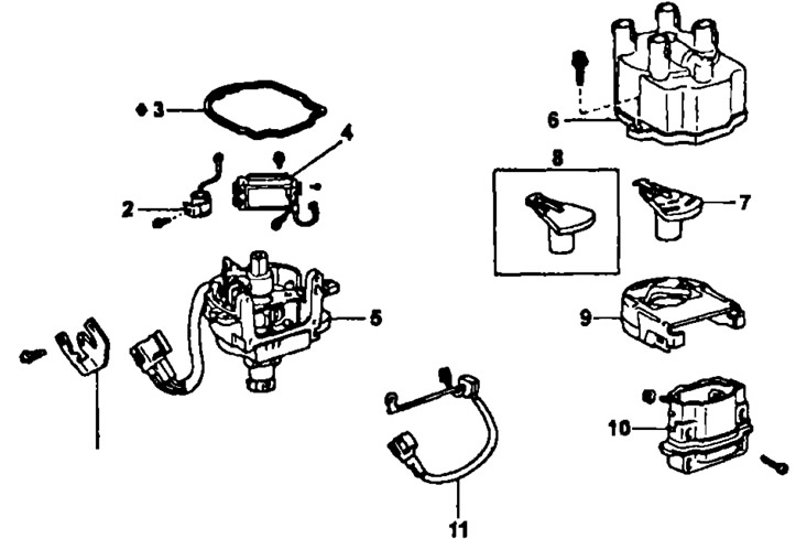
Distributor (3S-FE, 4S-FE, 5E-FE) or combined ignition unit (4A-FE, 7A-FE): t - wire clamp, 2 - capacitor, 3 - integrated ignition unit cover gasket (distributor caps), 4 - switch, 5 - housing of the combined ignition unit ("distributor body"), 6 - distributor cap, 7 - ignition distributor rotor, 8 - ignition distributor rotor (made of ceramic), 9 - ignition coil dust deflector, 10 - ignition coil, 11 - distributor wire
Removing
1. Remove a wire from the negative plug of the storage battery.
2. Disconnect the high voltage wires from the distributor cap.
- A) Using a screwdriver, pull the spring latch, lift up the fixing grip and disconnect the holder from the distributor cover;
- b) Disconnect the high voltage wires from the rubber bushings;
Note: Never pull on the wires as this may cause internal breaks in the wires.
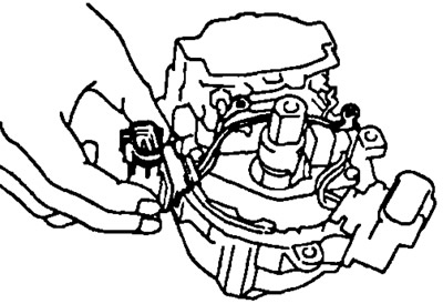
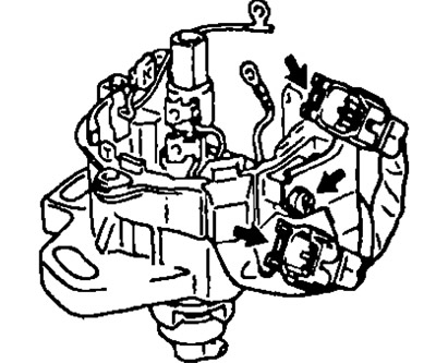
3. Disconnect the connectors from the combined ignition unit (block contactless ignition system) or from a distributor.
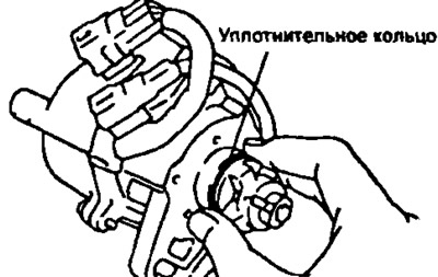
4. Remove the contactless ignition system unit (distributor), by unscrewing the two bolts securing the block.
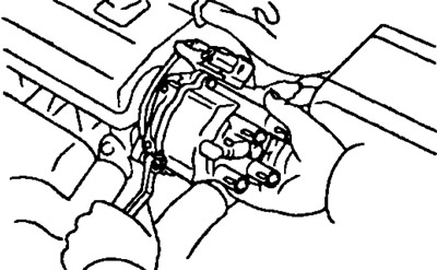
Then remove the O-ring seal from the distributor body.
Disassembly
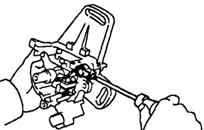
1. Remove the ignition distributor cover and gasket by unscrewing 3 bolts.
2. Remove the ignition distributor rotor.
3. Remove the dust deflector of the ignition coil along with the gasket.
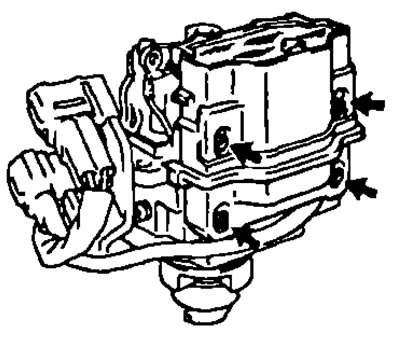
4. Remove the ignition coil.
- A) Disconnect three or four (depending on execution) wires from the ignition coil terminals by unscrewing 2 nuts.
- b) (3S-F£, 4S-FE) Remove the wiring connector from the distributor cap.
- V) Loosen 4 screws and remove the ignition coil.
- 5. (3S-FE, 4S-FE) Loosen the mounting screw and remove the capacitor.
7A-FE and 4A-FE (serial version)
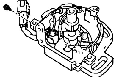
8. Remove the switch by first unscrewing 3 screws and disconnecting 3 wires from the switch terminals; then, after unscrewing the 2 fixing screws, remove the switch.
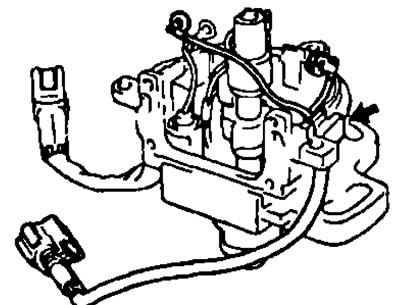
7. Remove the wire holder and distributor wiring (integrated ignition unit wiring harness):
- A) Disconnect the two connectors from the wire holder;
- b) Loosen the screw and remove the wire holder;
- V) Disconnect the distributor wire from the distributor housing.
6. Disconnect the capacitor by releasing the mounting bolt.
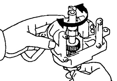
Distributor check
Turn the distributor shaft by turning it by hand, and make sure that the shaft rotates smoothly, without gaps and jamming.
If there is evidence of wear or seizing, replace the distributor housing.
Assembly
1. Install the capacitor.
7A-FE and 4A-FE (serial version)
2. Install the distributor wire and wire holder.
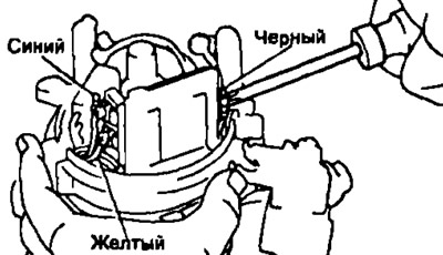
3. Install the switch by securing it with two screws and connecting three wires: black, blue and yellow to the switch terminals.
All engines
4. Install the ignition coil following the sequence.
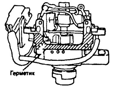
- A) Remove old sealant.
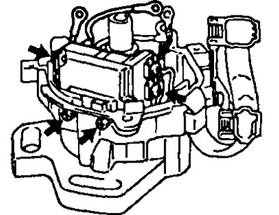
- b) Apply fresh sealant to the contact surface of the ignition coil housing that mates with the surface of the ignition unit housing as shown.
- V) Install and secure the ignition coil with 4 screws.
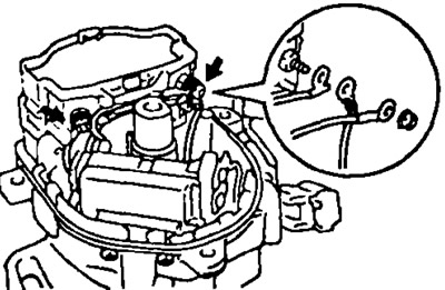
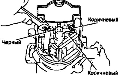
5. Connect the wires to the leads of the ignition coil, securing them with two nuts, as shown in the figure.
Note: in some versions on the motors, three wires must be connected: black and two brown.
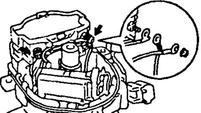
Note: When connecting the wires to the ignition coil, place the wires in the grooves provided on the side of the ignition coil.
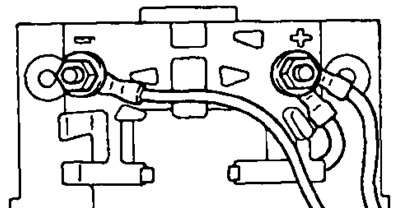
Note: Make sure the wires do not touch the encoder rotor or the integrated ignition unit housing.
6. Install the ignition coil dust deflector, after installing a new gasket under the housing cover of the combined ignition unit.
7. Establish a rotor of the distributor of ignition.
8. Install the distributor cap. fix it with 3 bolts.
Installation
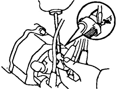
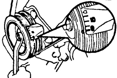
1. Bring the piston of the 1st cylinder to TDC By turning the engine shaft clockwise, align the mark "0" on the crankshaft pulley with a benchmark. The slot in the end of the camshaft should be located as shown in the figure.
4A-FE, 7A-FE | 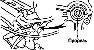
3S-FE, 4S-FE |
2. Install integrated ignition unit (block contactless ignition system) or distributor, following the sequence.
- A) Apply a coat of engine oil to the new O-ring seal housing.
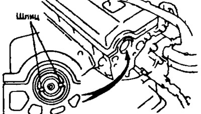
- b) Align the protrusion on the housing of the ignition unit (non-contact ignition system) or a distributor with a groove on the connecting sleeve.
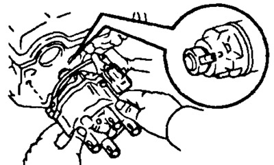
- V) Insert the ignition block (distributor), centering its mounting flange with the mounting hole in the cylinder head and aligning the holes of the ignition block flange with the holes for the mounting bolts in the cylinder head.
- G) Loosely fasten the two clamping bolts of the ignition unit (distributor).
3. Connect the high voltage wires to the distributor cap in accordance with the engine operating order: 1-3-4-2.
4. Connect the connectors of the combined ignition unit (block contactless ignition system).
5. Adjust ignition timing (see section "Ignition timing adjustment" in chapter "Maintenance and general inspection and adjustment procedures").
6. After adjusting the ignition timing, finally secure the integrated ignition unit housing to the cylinder head by tightening the fixing bolts. Tightening torque: 20 Nm.