
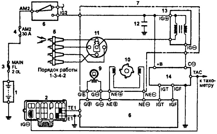
Wiring diagram of the ignition system (3S-FE, 4A-FE (serial version), 4S-FE, 5E-FE, 7A-FE): 1 - battery, 2 - diagnostic connector, 3 - main fuse "MAIN" ("FL 2,0L" - 3S-FE, 4S-FE; "FL 3W" - 4A-FE, 7A-FE), 4 - fusible insert "AM2" (30A), 5 - spark plugs, 6 - ignition lock, 7 - distributor and ignition coil, 8 - electronic engine control unit (electronic engine and automatic transmission control unit), 9, 10 - sensor rotor, 11 - cover and distributor rotor, 12 - capacitor, 13 - ignition coil, 14 - switch
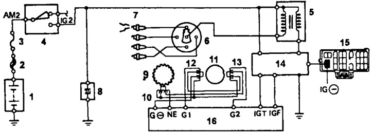
Wiring diagram of the ignition system (3S-GE, 4A-FE with Lean bum): 1 - battery, 2 - main fuse "2,0L", 3 - fuse "Am2" (30 A), 4 - ignition lock, 5 - ignition coil, 6 - cover and rotor of the ignition distributor, 7 - spark plugs, 8 - capacitor of the ignition system, 9 and 10 - rotor and inductive winding of the magnetoelectric crankshaft angle sensor, 11, 12, and 13 - rotor and inductive windings of the magnetoelectric camshaft angle sensor, 14 - switch, 15 - diagnostic connector of the switch, 16 - electronic engine control unit
1. (Integrated ignition system (block contactless ignition system)).
Disconnect the connectors of the combined ignition unit (block contactless ignition system), remove the cover and distributor rotor, as well as the dust deflector of the ignition coil.
2. (Ignition system with distributor) Disconnect the ignition coil connector and disconnect the high voltage wire from the ignition coil.
Checking the ignition coil
Note: terms "cold" And "hotter" state indicate the temperature of the windings:
- "cold" from -10°С to +50°С
- "hot". from +50°С to +100°С
These definitions are retained in the future also in relation to the inductive coils of the angular momentum sensors.
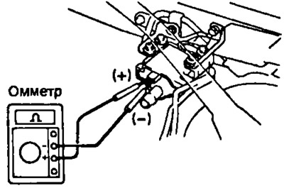
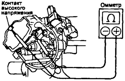
1. Check the resistance of the primary winding using an ohmmeter by connecting it to the ignition coil as shown in the figures.
3S-FE, 3S-GE, 4S-FE and 4A-FE (with lean boom system); 5E-FE:
- V «cold» state 0.36-0.55 ohm
- V «hot» state 0.45-0.65 ohm
7A-FE, 4A-FE serial version:
- V «cold» condition 1.11-1.75 ohm
- V «hot» condition 1.41-2.05 ohm
ZV-GE, 4A-FE (with Lean burn system) | 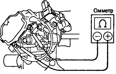
3S-FE, 4A-FE, 4S-FE, 5E-FE, 7A-FE |
2. Check the resistance of the secondary winding using an ohmmeter by connecting it to the ignition coil as shown in the figures.
7A-FE, 4A-FE (serial version):
- V «cold» condition 9.0-15.7 ohm
- V «hot» condition 11.4-18.4 ohms
3S-FE, 3S-GE, 4S-FE 4A-FE (with lean boom system), 5E-FE:
- V «cold» condition 9.0-15.4 ohm
- V «hot» condition 11.4-18.1 ohm
3S-FE, 4A-FE, 4S-FE, 5E-FE, 7A-FE | 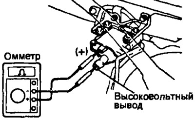
3S-GE, 4A-FE (with lean boom system) |
If the resistance of any of the ignition coil windings is not within specification, replace the ignition coil.
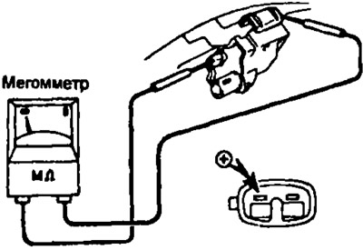
3. (4A-FE with Lean burn system) Using a megger, measure the insulation resistance between the positive terminal of the ignition coil (+) and high voltage wire output. Nominal resistance not less than 10 MOhm. Otherwise, replace the ignition coil.
4. (4A-FE with Lean bum) Connect the high voltage wire to the ignition coil as well as the ignition coil connector.
Distributor check
Disconnect the distributor connector, remove the distributor cap and spark distributor rotor.
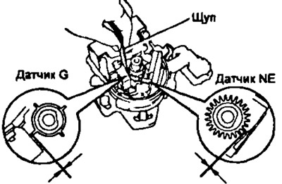
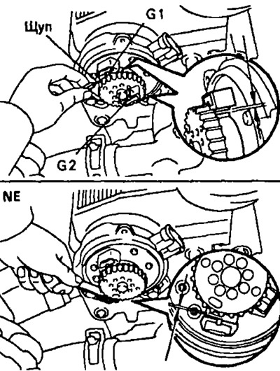
1. Using a feeler gauge, check the air gap between the teeth of the rotor of the angular impulse sensors and the protrusion of the core of the inductive coil of this sensor.
Note; if several angle pulse sensors are used in the ignition system (crankshaft position sensor NE and camshaft angle sensors G, G1, G2), then similar measurements should be performed for each sensor.
4A-FE (serial version), 7A-FE | 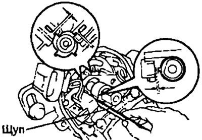
3S-FE, 4S-FE, 5E-FE |
3S-GE, 4A-FE (with lean boom system)
Nominal air gap: 0.2-0.4mm.
If clearance is out of specification, replace distributor housing, distributor assembly, or integrated ignition housing (block contactless ignition system).
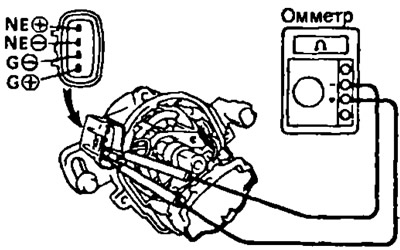
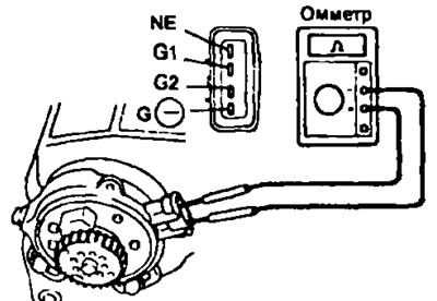
2. Using an ohmmeter, check the electrical resistance of the inductive coils of the crankshaft and camshaft angle pulse sensors. The ohmmeter connection diagrams are shown in the figures, and the pin numbers to which the ohmmeter must be connected, and the nominal resistance values of the inductive coils of the angular pulse sensors are given in the table "The value of the electrical resistance of the inductive coils of the sensors of angular impulses".
3S-FE, 4S-FE, 5E-FE, 7A-FE and 4A-FE (serial version):
IN "cold" condition:
- G (+) and G (-) 185-275 ohm
- NE (+) and NE (-) 370-550 ohm
IN "hot" condition:
- G (+) and GN 240-325 Ohm
- NE (+) and NE (-) 475-850 Ohm
3S-GE:
IN "cold" condition:
- G1 and G (-) and G2 and G (-) 140-180 ohm
- NE (+) and G (-) 180-220 ohm
4A-FE with Lean bum:
IN "cold" condition:
- G1 and G (-) and G2 and G (-) 125-200 ohm
- NE (+) and G (-) 155-250 ohm
IN "hot" condition:
- G1 and G (-) and G2 and G (-) 160-235 ohm
- NE (+) and G (-) 190-290 ohm
3S-FE, 4S-FE | 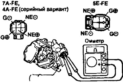
7A-FE, 4A-FE (serial version) |
3S-GE, 4A-FE (with lean boom system)
If the resistance is not within the specified limits, replace the entire valve assembly (housing of the integrated ignition unit).
3. (Only for ignition systems with integrated ignition unit (block contactless ignition system)) Install ignition coil dust deflector, distributor rotor. distributor cap, connect the connectors of the combined ignition unit (block contactless ignition system).
4. (Only for ignition systems of engines with a distributor) Reinstall the distributor rotor. distributor cap and connect the distributor connector.