
Examination
2. When performing the test, slightly raise the engine (or a gearbox in a block with a drive axle), to unload the supports.
3. Raise the vehicle and place secure supports under it. Remove the lower engine cover (see paragraph 6) and place a jack under the oil pan. Place a large block of wood between the jack and the oil pan, and then carefully lift the engine up just enough to take the pressure off the mounts. Do not place a block of wood under the oil drain plug.
Attention! Do not work under the engine when it is only supported by a jack.
Attention! If the vehicle is equipped with electronically controlled air suspension, turn off the suspension height control switch.
4. Check the mounts for cracks in the rubber, hardening of the rubber and separation from the bushing at the center of the mount.
5. Check for relative movement between skid plates and motor or frame. When attempting to move the supports, use a large screwdriver or pry bar.
6. If there is movement, lower the engine and tighten the fasteners.
Replacement
7. Disconnect the ground wire from the battery (see paragraph 1 of chapter 5). Raise the vehicle and securely support it under it, if you have not already done so. Support the engine as described in point 3.
Attention. If the vehicle is equipped with electronically controlled air suspension, turn off the suspension height control switch.
Note. If several supports need to be replaced at once, replace them only one at a time with the obligatory tightening of each until it stops. Do not remove all supports at once.
Passenger side engine mount (right)
8. Working under the vehicle, remove the nuts securing the support to the upper and lower brackets (pic. 17.8).
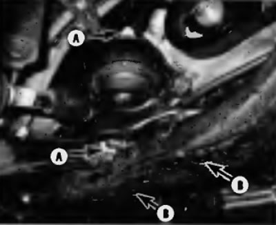
Pic. 17.8. nuts (A) and bolts (IN) right support of the power unit (there are bolts under the covers)
9. Turn out bolts of fastening of a support to a frame, then raise the engine so that it was possible to remove support.
Note. To raise the engine enough to give enough room to remove the passenger side engine mount, you will need to loosen the mounting nuts on the other power unit mounts on the subframe.
10. Installation is carried out in sequence. reverse withdrawal. Apply thread locking compound to the bolts, screw in the bolts and tighten them securely
Transmission support in the block with the drive axle on the driver's side (left)
11. Working under the vehicle, remove the nut securing the support to the top and bottom brackets.
12. Turn out bolts of fastening of a support to a frame, then raise a transmission in the block with the driving axle so that it was possible to remove a support.
Note. To raise the engine enough to give enough clearance to remove the transaxle mount on the driver's side, it will be necessary to loosen the mounting nuts on the other powertrain mounts on the subframe.
13. Installing is performed in the reverse order of removal. Coat the bolts with thread locking compound, screw in the bolts and tighten securely.
Front engine mount
14. Working under the vehicle, remove the nut securing the engine support bracket to the support.
15. Turn out bolts of fastening of a support to a frame, then raise the engine so that it was possible to remove a support.
Note. To raise the engine enough to allow room to remove the driver's side front engine mount, you will need to loosen the mounting nuts on the other powertrain mounts on the subframe.
16. Installation is carried out in the reverse order of removal. Coat the bolts with thread locking compound by screwing in the bolts and tighten them securely.
Rear engine mount
17. Working under the vehicle, remove the nut securing the engine support bracket to the support.
18. Turn out bolts of fastening of a support to a frame, then raise the engine so that it was possible to remove a support.
19. Installation is carried out in the reverse order of removal. Coat the bolts with thread locking compound, install the bolts and tighten them securely.
Tie rod engine mount
20. Working in the engine compartment, remove the bolts securing the jet thrust of the engine mount and its bracket (pic. 17.20).
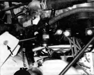
Pic. 17.20. Location of engine mount tie rod bolts
21. Installation is carried out in the reverse order of removal. Coat the bolts with thread locking compound, remove the bolts and tighten them securely.