
Disconnect the negative battery terminal.
Remove the battery.
Remove the battery tray.
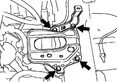
Pic. 2.183. Bolts of fastening of a platform of the accumulator battery
Remove the 4 mounting bolts, then remove the platform and battery bracket (pic. 2.183).
Remove the air filter cover assembly.
Disconnect the engine harness clamp.
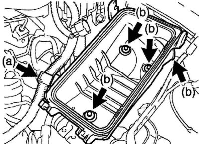
Pic. 2.184. Removing the air filter housing
Remove the 3 bolts and remove the No. 1 air filter inlet, then remove the air filter housing (pic. 2.184).
Disconnect the fuel supply line.
Disconnect the hose connecting to the fitting.
Disconnect the heater inlet pipe.
Disconnect the heater outlet (from the heater).
Disconnect the shift cable assembly (Manual Transmission).
Disconnect the clutch slave cylinder assembly (Manual Transmission).
Remove the fan and alternator V-belt.
Remove the generator assembly.
Remove the A/C compressor with pulley assembly (for vehicles with air conditioning).
Note. In order not to discharge the air conditioning system, secure the compressor and hoses to the side.
Loosen the nut and disconnect the engine wiring harness.
Disconnect the connector.
Disconnect the wiring harness by pulling it up.
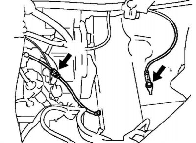
Pic. 2.185. Ground terminal and connector
Remove the bolt, then disconnect the ground terminal, disconnect the ground connector (pic. 2.185).
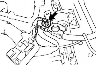
Pic. 2.186. Battery terminal B
Loosen the nut, then disconnect the battery terminal B (pic. 2.186).
Remove the front exhaust pipe assembly.
Remove a noise-proof overlay of a casing of an exit aperture of a steering column.
Disconnect the #2 intermediate steering shaft assembly.
Loosen the nut on the left front axle hub.
Loosen the nut on the right front axle hub.
Disconnect the left front stabilizer link.
Disconnect the right front stabilizer link
Disconnect the left front wheel speed sensor.
Disconnect the right front wheel speed sensor.
Disconnect the right and left tie rod ends.
Disconnect the left and right lower control arms of the No. 1 front suspension.
Disconnect the left and right parts of the front axle assembly.
Install the engine lift.
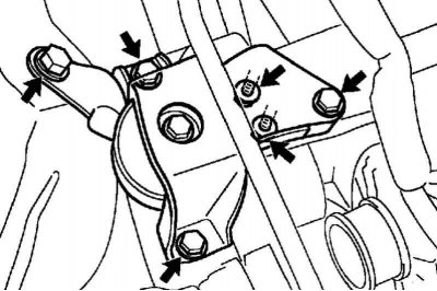
Pic. 2.187. Bolts of fastening of the right pillow of a support of the engine
Remove 4 bolts and 2 nuts, then remove the right engine mount pad (pic. 2.187).
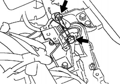
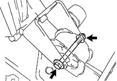
Pic. 2.188. Coupling bolt of the left pillow of a support of the engine
Loosen the pinch bolt and nut, then remove the left engine mount pad (pic. 2.188).
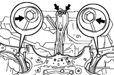
Pic. 2.189. Front subframe bracket nuts
Turn out 2 bolts and turn away 2 nuts, as it is shown in drawing 2.189.
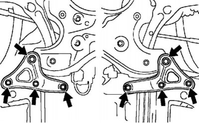
Pic. 2.190. Bolts for fastening the rear right and left brackets of the front suspension subframe
Remove the 8 mounting bolts and remove the rear right and left brackets of the front suspension subframe (pic. 2.190).
Carefully remove the engine and transmission assembly from the engine compartment.
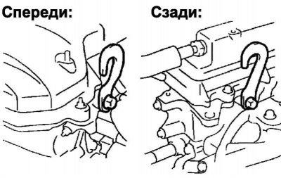
Pic. 2.191. Hooks for hanging engines
Install the hook for hanging the engine (12281-22021) and fasten it with a bolt (91512-B1016) (pic. 2.191).
Tightening torque: 38 Nm.
Install hook for hanging engine No. 1 (12281-15040) and fasten it with a bolt (91512-B1016) (pic. 2.191).
Tightening torque: 38 Nm.
Attach a cable to the engine and hang the engine on a hoist.
Remove the power steering pump assembly.
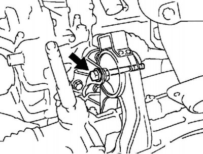
Pic. 2.192. Coupling bolt, front subframe bracket
Loosen the pinch bolt and nut, then remove the engine mount pad from the front subframe bracket (pic. 2.192).
Pic. 2.193. Subframe Rear Bracket Coupling Bolt
Loosen the pinch bolt and nut, then remove the rear engine mount pad from the rear subframe bracket (pic. 2.193).
Disconnect the engine and transmission assembly from the suspension subframe and from the engine mount.
Remove the front left and right drive shaft assemblies.
Remove the starter assembly.
Remove the manual transmission assembly (Manual Transmission).
Remove the clutch basket assembly.
Remove the clutch disc assembly and flywheel.
Remove the ignition coil assembly.
Remove the injector rail assembly.
Remove the intake manifold.
Disconnect the crankshaft position sensor mount.
Pic. 2.194. Bolt of fastening of a tube of an oil dipstick
Unscrew the bolt and remove the oil dipstick tube (pic. 2.194).
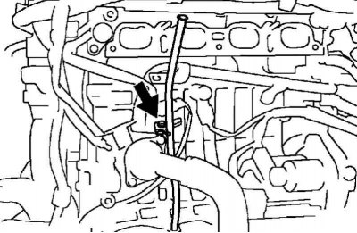
Disconnect the knock sensor mount.
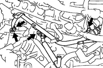
Pic. 2.195. Fastening of a bypass pipe No. 1 of the cooling system
Turn out 2 bolts, turn off 2 nuts and remove bypass pipe No. 1 of the cooling system (pic. 2.195).
Remove the gasket from the cylinder block.
Remove the inlet pipe of the engine cooling system.
Remove the thermostat
Remove the engine oil pressure sensor.
Remove the camshaft angle sensor.
Remove the crankshaft position sensor.
Remove the knock sensor.
Remove the V-ribbed belt tensioner assembly.
Remove the manifold bracket.
Remove manifold bracket #2.
Disconnect the heated oxygen sensor connector.
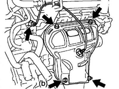
Pic. 2.196. No. 1 heat shield mounting, exhaust manifold
Remove the 3 bolts, remove the nut and remove the exhaust manifold heat shield No. 1 (pic. 2.196).
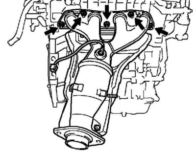
Pic. 2.197. exhaust manifold mounting
Remove 5 nuts, then remove the exhaust manifold (pic. 2.197).
Remove the gasket from the cylinder head.
Remove the coolant temperature sensor.
Turn out a bolt and remove a set of details for installation of a radio tape recorder and the additional equipment.
Remove bypass pipe No. 2 of the cooling system
Disconnect the radiator inlet hose
Disconnect the heater inlet
Remove the engine without attachments.
Note. Installation and assembly of engine components is carried out in the reverse order of removal.