
Attention! Wait until the engine has completely cooled down before starting this procedure.
Removing
1. Relieve pressure in the fuel system (see chapter 4), then disconnect the ground wire from the battery (see paragraph 1 of chapter 5).
2. Remove the suspension strut tie and remove it from the engine compartment (in the presence of) (see paragraph 3 of chapter 10).
3. Drain engine coolant (see chapter 1).
4. Disconnect the coolant hoses from the cylinder head (see chapter 3).
5. Remove the drive belt (see chapter 1).
6. Remove generator (see chapter 5).
7. Remove intake manifold (see paragraph 8) and the intake manifold support pad.
8. Remove the cylinder head cover (see paragraph 4)
9. Remove the throttle body, fuel injectors and fuel rail (see chapter 4).
10. Remove the exhaust manifold (see paragraph 9) and exhaust manifold brackets.
11. Remove the timing chain and camshaft sprockets (see paragraph 6).
Note. Instead of supporting the engine from above with a special yoke or lifting device, it should be supported from below with a jack with a wooden block installed on its head, but only after removing the stamped steel section of the oil pan.
12. Remove camshafts and tappets (see paragraph 7).
13. Remove variable valve timing oil control valve (rice. 5.2, b).
14. Label and disconnect the electrical connections on the cylinder head.
15. Using a 10 mm 12-point bit and an extension, in stages, ¼ turn per approach, loosen the cylinder head bolts until they can be unscrewed manually. To avoid deformation of the cylinder head and the appearance of cracks in it, loosen the bolts in the reverse order of the recommended tightening sequence (pic. 10.27).
16. Remove the cylinder head from the cylinder block. If it does not come off, very carefully pry off the end of it from the side of the gearbox in the block with the drive axle, outside the area of the gasket.
17. Remove all other external elements from the cylinder head so that a full-scale cleaning and inspection can be performed.
Installation
18. When installing the cylinder head, the mating surfaces of the head and cylinder block must be completely clean.
19. Use a scraper to remove all carbon deposits and old gasket materials, and then clean the mating surfaces with lacquer thinner or acetone. If there is oil on non-mating surfaces when the cylinder head is installed, the gasket may not seal properly and leakage will occur. When working with the block, stuff the cylinders with a clean rag so that dirt does not penetrate into them. Use a vacuum cleaner to remove dirt that has entered the cylinders
20. Check mating surfaces of the block and cylinder head for nicks, deep scratches and other damage. If the damage is insignificant, it can be fixed with a file; if it is large, machining may be the only option.
21. Using a tap of the proper size, calibrate the threads in the holes for the cylinder head bolts, and then blow out the holes with compressed air. Check that nothing is left in the holes.
Attention! Always wear eye protection when working with compressed air.
22. Using a weeder brush, clean the threads of each bolt to remove any traces of corrosion and restore thread profile. Dirt, corrosion products, sealant and thread damage will affect the tightening torque. Measure the length of each bolt from the underside of the head to the end and compare the result with the value given in the Specifications at the beginning of this chapter. Replace any bolts that are stretched beyond the maximum allowable length. If the bolts are damaged in any way, replace them with new ones.
23. Establish elements which have been removed from a head of cylinders.
24. Install a new gasket, following the dowel pins on the block so that the identification mark «lot numbers» was facing up. Then apply RTV Sealant to the areas at the end of the cylinder head gasket as shown (rice. 6.33b).
25. Carefully install the cylinder head on the block without moving the gasket.
26. Before screwing in the cylinder head bolts, apply a little clean engine oil to the threads and the surface under the bolt heads.
27. Screw in the bolts (with washers) according to the starting positions and tighten by hand. Following the recommended sequence, tighten the bolts to the specified torque specified in Specifications at the beginning of this chapter (pic. 10.27). Stage 2 tightening requires turning each bolt an additional 90°. If you do not have an angle torque wrench, simply paint a mark on one face of each bolt and tighten the bolts until the mark rotates 90° (¼ turn) from the starting position.
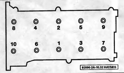
Pic. 10.27. Cylinder head bolt tightening sequence
28. The rest of the installation is carried out in the reverse order of removal.
29. Check and, if necessary, adjust the valve clearances (see chapter 1)
30. Change engine oil and oil filter (see chapter 1).
31. On all-wheel drive models, refuel the transfer case (see chapter 1).
32. Fill the cooling system (see chapter 1), start the engine and check for leaks.