
Attention! Wait until the engine has completely cooled down before starting this procedure.
Note. This procedure requires special tools. Before starting work, carefully read the contents of the procedure and prepare the necessary tools and equipment.
1. Disconnect the ground wire from the battery (see paragraph 1 of chapter 5).
2. Remove the drive belt (see chapter 1) and generator (see chapter 5).
3. Remove the cylinder head cover (see paragraph 4).
4. Apply the parking brake and chock the rear wheels. Loosen the nuts on the right front wheel. Raise the front of the car and place secure supports under it. Remove the right front wheel and corresponding locker.
Attention! If the vehicle is equipped with electronically controlled air suspension, turn off the suspension height control switch.
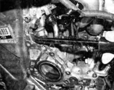
5. Remove the lower engine protection (pic. 6.5). Remove fender flares (see chapter 11).
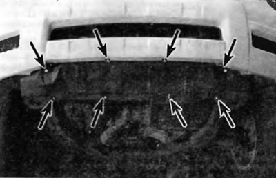
Pic. 6.5. The location of the lower engine protection mounting elements on newer Highlander models
6. Drain the coolant from the cooling system (see chapter 1). While the coolant is draining, remove the power steering pump from the engine without disconnecting the hydraulic lines from it (see chapter 10). Tie the booster pump to the body with a piece of wire and position it to the side.
7. Disconnect front exhaust pipe from exhaust manifold/catalytic converter (see chapter 4).
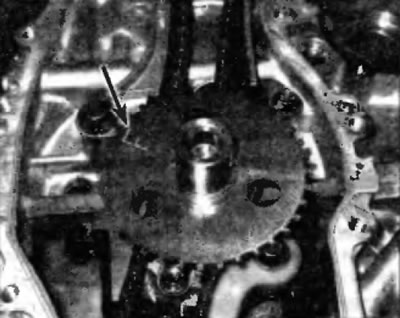
8. Bring the No. 1 piston to TDC on the compression stroke (see paragraph 3). Visually verify that the engine is at TDC on the compression stroke - the alignment mark on the crankshaft pulley/damper is aligned with the mark «0» on the timing chain cover, and the mark on the camshaft sprocket is aligned and parallel to the top edge of the timing chain cover (pic. 6.8).
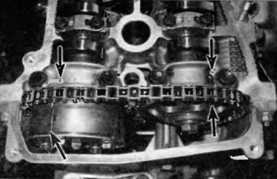
Pic. 6.8. When the engine is at TDC, the marks on the camshaft sprockets (bottom arrows) aligned with marks on camshaft bearing caps (top arrows)
Note. There are two sets of marks on the camshaft sprockets. The marks that align at the TDC position are only reference marks for the TDC position and nothing more: two other marks are used to align the sprockets for the purpose of the gas distribution mechanism during installation.
9. Remove the crankshaft pulley/damper, being careful not to pull the engine out of TDC (see paragraph 11). If the engine is moved out of TDC when following this step, return the engine to TDC again before proceeding. The engine must remain at TDC for piston #1 throughout the procedure.
10. Support the engine from above using the engine support bar (it can be rented).
11. Remove passenger side engine mount and engine mount tie rod (see paragraph 17). Remove the front engine support and transmission support in the block with the drive axle (see paragraph 17).
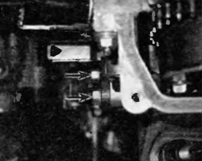
12. Remove the drive belt tensioner (pic. 6.12) and the crankshaft position sensor from the timing chain cover. Also remove the crankshaft position sensor wiring harness bolt to the timing chain cover.
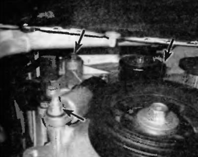
Pic. 6.12. Fastening elements of the drive belt tensioner
13. Remove the oil pan (see paragraph 13).
14. Turn out bolts of fastening of the main plait of electroconducting and remove a tensioner of a timing chain from the back party of a cover of a timing chain (pic. 6.14, a, b).
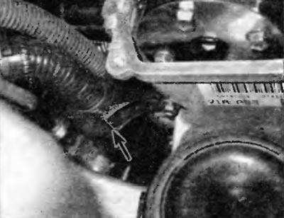
Pic. 6.14 a. Remove the two bolts securing the main wiring harness to the timing chain cover
Pic. 6.14b. Nuts of fastening tensioners of a chain of the gas-distributing mechanism
15. Turn out bolts of fastening of a cover of a chain of the gas-distributing mechanism (note the diameter, location and length of the screws when they are removed as they should be reinstalled in their original locations) and remove the engine cover (pic. 6.15, a-d).
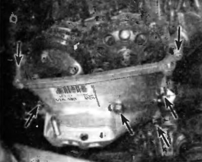
Pic. 6.15 a. Top screws securing the timing chain cover
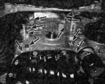
Pic. 6.15 b. Upper screws for fastening the cover of the price of the gas distribution mechanism
Pic. 6.15, in. You will need to unscrew the studs securing the timing chain cover...
Pic. 6.15,...and only son-in-law to shine the cover from the engine
16. Remove the crankshaft position sensor impulse wheel from the crankshaft. Pay attention to the label «E» not front side (after installation, it must face outwards) (pic. 16.16).
Pic. 6.16. Remove the crankshaft position sensor pulse wheel from the shaft (label «F» arrow)
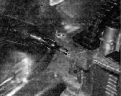
17. Remove tensioner arm/timing chain guide and lower chain guide (pic. 6.17).

Pic. 6.17. Timing chain guide fastening
A Articulated bot
B Tensioner arm/chain guide
C Fixed chain guide bolts
D Fixed chain guide
E Lower timing chain guide
18. Remove the timing chain from the camshaft sprockets, and then remove the chain and crankshaft sprocket from the engine as a single assembly. The crankshaft sprocket must be removed from the shaft by hand. If the sprocket does not come off the shaft, carefully pry it off with a lever.
Note. If you intend to use a timing chain and delta, mark with white paint or chalk to indicate the front of the chain. If the removed timing chain with characteristic one-sided wear is reinstalled in the opposite direction, noise and increased wear may occur.
19. Remove the fixed timing chain guide (pic. 6.17).
20. To remove the sprockets from the camshafts, loosen the bolts while holding the shafts with a wrench only by the hex section. Before removal, pay attention to the identification marks on the camshaft sprockets, and then remove the bolts. Pull the sprockets by hand to remove them from the pins. If necessary, use a small puller to remove the sprockets. With grippers inserted into the holes provided on the sprockets.
Note. The models in question are equipped with a variable valve timing system, which includes an actuator connected to the intake camshaft sprocket. When removing the sprocket from the intake camshaft on these models, only loosen and remove the central bolt that secures the sprocket to the shaft. Do not loosen the outer four bolts that hold the actuator to the sprocket.