



Caution: Wait until the engine has cooled down completely before starting this procedure.
Removal
1. Relieve the pressure in the fuel system (see chapter 4). Disconnect the ground wire from the batteries (see paragraph 1 of chapter 5).
2. Remove the air intake duct (see chapter 4).
3. Remove the fuel rail and injectors as a single assembly (see chapter 4). Remove the throttle body (see chapter 4).
4. Tag and disconnect the positive crankcase ventilation hoses and the vacuum hoses connected to the intake manifold (Fig. 8.4). Raise the vehicle and support it securely.
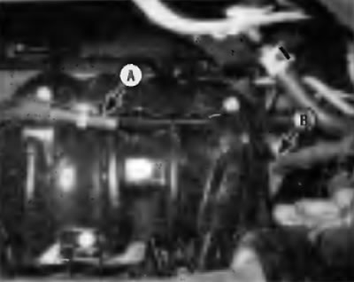
Fig. 8.4. Label the vacuum hose(s) (A) and disconnect it(them) from the intake manifold, remove the wiring harness retainer (B)
Caution: If the vehicle is equipped with electronically controlled air suspension, turn off the ride height control switch.
Note. If you are working with all-wheel drive (4WD), loosen the right half-axle/hub nut before lifting the vehicle (see chapter 8) and the nuts of the right front wheel.
All-wheel drive (4WD) options
5. Drain the transmission oil from the transfer case (see chapter 1).
6. Remove the right axle shaft (see chapter 8).
7. Separate the support from the transfer case. Remove the transfer case support brace.
All models
8. Working under the vehicle, unscrew the lower manifold mounting bolts (Fig. 8.8).
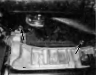
Fig. 8.8. Location of lower intake manifold mounting bolts
9. Working from the top, loosen the nuts and remove the manifold mounting bolts. Remove the manifold, gasket and manifold support pad from the engine (Fig. 8.9).
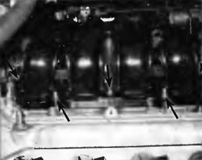
Fig. 8.9. Location of the upper intake manifold fastening elements
Installation
10. Clean the mating surfaces of the intake manifold and cylinder head with lacquer thinner or acetone. If the gasket shows leakage marks, check the manifold mating surface for flatness with a straight edge and feeler gauge. If the mating surface is warped, the manifold should be replaced.
11. Insert a new gasket into the groove on the manifold (Fig. 8.11). Install the manifold and gasket, using the studs on the cylinder head as a guide.
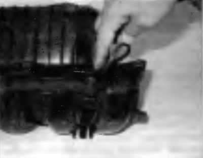
Fig. 8.11. Insert the gasket into the groove on the intake manifold
12. Tighten the manifold-to-cylinder head nuts/bolts evenly in three or four stages to the specified torque specified in Specifications at the beginning of this chapter. Start with the top bolts to avoid distorting the manifold.
13. Install the remaining components in the reverse order of removal. Check the coolant level and top up if necessary (see chapter 1).
14. On all-wheel drive models, fill the transfer case (see chapter 1).
15. Before starting the engine, check the smooth operation of the accelerator cable (if available).
16. Start the engine and check for coolant and vacuum leaks.
17. Perform a road test of the vehicle and check the reliability of all auxiliary systems and units, including the cruise control system (if available).
View the original source on the website ToyotaMAN.ru