
1.6L petrol engine (4A-F, 4A-FE)
Removing
Remove cylinder head cover with gasket.
Install piston first cylinder at TDC.
Attention: Do not change the position of the crankshaft in the future.
Remove toothed belt.
Remove ignition distributor.
Remove the mechanical fuel pump from the cylinder head, if it exists.
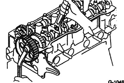
Loosen the camshaft wheel bolt, holding the wheel from turning with an adjustable wrench, eg HAZET 279-15. Remove the wheel, using a rubber mallet if necessary.
Attention: When holding the camshaft from turning, do not damage the cylinder head with a wrench.
Check camshaft end play. Its value should be within: intake valve shaft 0.03-0.08 5mm; exhaust valve shaft 0.03-0.09 mm. The maximum allowable axial play must not exceed 0.11 mm. If the axial play exceeds the specified value, then the camshaft, and possibly the cylinder head, must be replaced.
Attention: Since the camshaft end play is very small, the shaft must be kept in a horizontal position during disassembly. To ensure this, the following conditions must be met. If the camshaft is warped during disassembly, it or the cylinder head may be damaged.
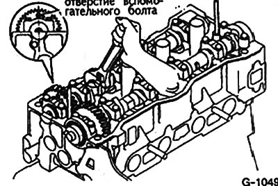
Turn the camshafts so that the hole for the auxiliary bolt on the gear wheel of the intake camshaft is in the position shown in the figure.
In several steps, unscrew the bolts securing the bearing caps No. 1 of the intake and exhaust camshafts. Remove covers.
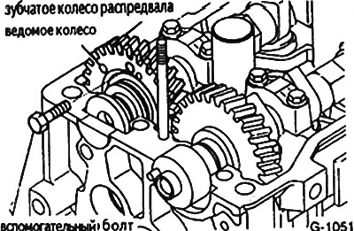
Tighten with an M6x1.0 screw 16-20 mm long an additional gear and gear of the intake camshaft.
Attention: When removing the camshaft, make sure that the spring between the gears is fully compressed by the screw.
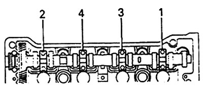
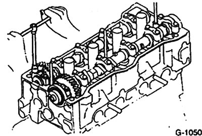
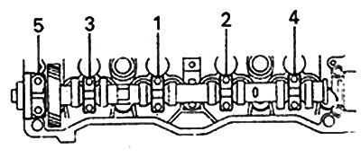
Unscrewing evenly, in the sequence shown in the figure, remove the bearing caps.
Caution: Do not use force or any tool to remove the camshaft. If the camshaft cannot be removed, then the last removed bearing cap must be reinstalled. (Pic. G-1052, #4) and re-tighten the bolts and fasteners. Then, gradually unscrewing the bolts, simultaneously pull up the camshaft.
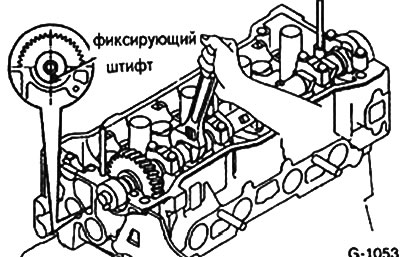
Rotate the exhaust camshaft 105°until the locking pin is in the position shown in fig. G-1053.
Loosen the bearing cap bolts in several steps in the sequence shown in Fig. G-1052.
Remove the exhaust camshaft bearing caps and pull out the shaft.
Attention: Do not remove the camshaft using force or any tool. If the camshaft cannot be removed, then the last removed bearing cap must be reinstalled (Pic. G-1052 #4) and tighten the mounting bolts. Then, gradually unscrewing the bolts, simultaneously pull up the camshaft.
Installation
Attention: Since the camshaft end play is very small, the shaft must be kept horizontal during installation. To ensure this, the following conditions must be met. If the camshaft is warped during installation, it may be damaged or the cylinder head may be damaged.
Apply a thin coat of oil to all camshaft bearings.
Install the camshaft so that the locating pin for centering the camshaft wheel is in the position shown in Fig. G-1053.
Apply sealant N 102 (ET-Nr.08826 00080) or any other sealant or silicone base as shown in fig. Tighten the mounting bolts by hand.
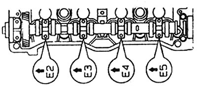
Install the camshaft bearing caps in accordance with the arrow numbers stamped on them in the direction of the gear and fasten them by hand with bolts.
The exhaust camshaft bearing caps are marked with the letter "E", the intake camshaft bearing caps are marked with the letter "T".
Tighten the bearing cap bolts in two steps with a torque wrench in the sequence shown in fig. with the following efforts:
- 1 pass - 10 Nm
- 2 reception - 13 Nm
Install a new camshaft seal using light blows with a rubber mallet. TOYOTA specialist workshops use the special tool SST 09223-46011 for this. If the specified tool is not available, a pipe with an outer and inner diameter equal to the gland diameters can be used. Lubricate the contact points lightly with oil.
Attention: Do not distort the gland during installation.
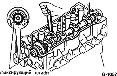
Set the locking pin of the exhaust camshaft to the position shown in fig.
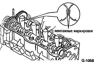
Insert the intake camshaft so that the gears of both shafts engage and the markings match.
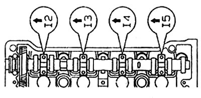
Install the bearing caps in accordance with the markings stamped on them so that the arrows point towards the gear. Tighten the screws by hand.
The caps mounted on the exhaust camshaft bearings are marked "E", the intake camshaft covers are marked "T".
Attention: do not confuse the bearing caps.
Tighten the bearing cap bolts with a torque wrench following the sequence shown in Fig. G-1056. The tightening is performed in two steps.
- 1 step - tightening force 10 Nm
- 2 reception - tightening force 13 Nm
Remove the auxiliary screw from the additional gear and the main gear.
Reinstall bearing caps #1. Fasten them by hand with bolts and tighten in two steps.
- 1 step - tightening force 10 Nm
- 2 reception - tightening force 10 Nm
Turn the camshaft one revolution from TDC to TDC of the first cylinder. The piston of the first cylinder is at TDC if the camshaft gear locking pin is vertically above the camshaft axis.
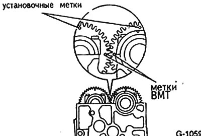
Check if the TDC markings on the rear sides of the gears match. The markings on the front of the gears must be vertical. If this condition is not met, then the intake camshaft must be removed and reinstalled.
Clean the camshaft gear from water and oil.
Install the wheel so that the pin matches the hole. Tighten the bolt to 60 Nm while holding the camshaft from turning with an adjustable wrench.
Attention: Be careful not to damage the cylinder head with the key.
Install the camshaft wheel so that the hole in the wheel is vertically above the mounting bolt.
Put on the toothed belt and tighten it.
Check valve clearances.
Install the cylinder head cover with gasket.