
Removing
Removal in the following order:
- remove the oil pan;
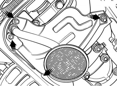
Pic. 3.39. The location of the bolts and nuts for fastening the oil receiver with a reflective plate and a strainer
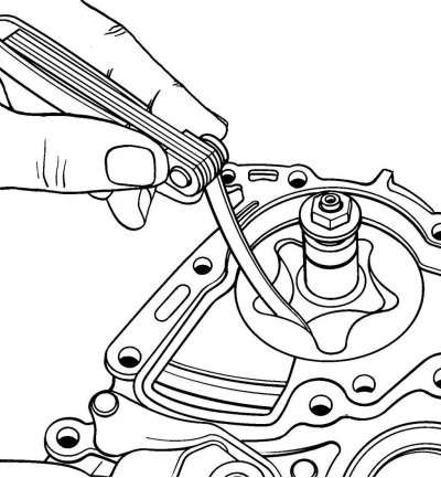
- remove 2 nuts and 2 bolts (pic. 3.39) and remove the oil receiver with a reflective plate and a strainer;
- support the engine from above and remove the idler pulley, V-ribbed belt pulley from the crankshaft, toothed belt and toothed belt pulley;
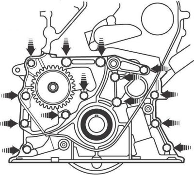
Pic. 3.40. Arrangement of bolts of fastening of a forward cover with the case of the oil pump
- remove 12 bolts (pic. 3.40) and remove the front cover with the oil pump housing from the cylinder block;
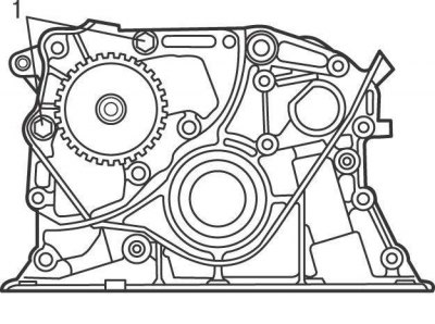
Pic. 3.41. Bolt location (1) fixing the cover to the oil pump housing
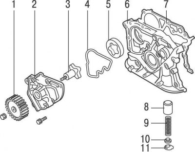
Pic. 3.42. Oil pump: 1 - pulley; 2 - cover; 3 - drive gear; 4 - sealing gasket of round section; 5 - driven gear; 6 - front cover with oil pump housing; 7 - gasket; 8 - piston of the pressure reducing valve; 9 - spring; 10 - spring seat; 11 - retaining ring
- remove two screws 1 (pic. 3.41) and remove the cover from the oil pump housing. Remove driven gear 5 (pic. 3.42) oil pump and sealing gasket 4 round section;
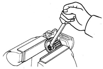
Pic. 3.43. Unscrewing the nut securing the oil pump pulley
- fix the oil pump pulley in a vice with soft jaws and unscrew the pulley fastening nut (pic. 3.43). Remove the oil pump shaft from the drive gear;
- with a hard plastic or wooden scraper, clean the mating surfaces of the oil pump housing and cover from the remnants of the old gasket and sealant;
- remove the pressure reducing valve retaining ring, spring seat, pressure reducing valve spring and piston.
Examination
Clean all parts of the oil pump and inspect them for damage.
Inspect the relief valve piston for wear and tear. Otherwise, replace the pressure reducing valve piston and spring as a set.
Using a feeler gauge blade, check the clearance between the driven gear of the pump and the housing. The nominal value of the gap is 0.10–0.16 mm, the maximum allowable value is 0.20 mm. If the clearance exceeds the limit, replace the oil pump drive and driven gears as a set and the oil pump housing.
Pic. 3.44. Measuring the gap between the driven and driving gear of the oil pump
Use a feeler blade to check the clearance between the driven and driving gears of the pump (pic. 3.44). The nominal value of the gap is 0.04–0.16 mm, the maximum allowable value is 0.20 mm. If the clearance exceeds the limit, replace the oil pump driven and driving gears as a set.
Installation
Install in the following order:
- use a screwdriver blade to remove the old and install a new o-ring in the oil pump cover. Lubricate the sealing lip with fresh engine oil;
- Replace the O-ring in the oil pump housing in the same way. Lubricate the sealing lip with fresh engine oil;
- install a new O-ring in the oil pump housing;
- lubricate the driven gear of the oil pump with fresh engine oil and install it in the housing so that the mark on the gear is located on the side of the oil pump cover;
- Lubricate the bearing and pinion shaft with fresh engine oil and install the shaft into the housing. Install the pulley on the shaft and secure it with a nut, tightening it with a torque of 24 Nm;
- install the oil pump cover and fix it with two bolts 16 mm long, tightening them with a torque of 9 Nm;
- lubricate the pressure reducing valve piston with fresh engine oil and install all valve parts in the oil pump housing;
- check that the guide bushings are installed in the cylinder block.
- install the gasket on the guide bushings;
- install the oil pump housing and secure with bolts, tightening them in several passes to a torque of 9 Nm;
- install with a new gasket or o-ring the oil receiver with baffle plate and strainer and secure with bolts and nuts, tightening them to a torque of 5.5 Nm (see fig. 3.39).
Further installation is carried out in the reverse order of removal, taking into account the following.
Fill the engine with engine oil.
Start the engine and check the oil pressure and for leaks.
Check engine oil level.