
Attention! To adjust the gaps, you will need a special tool for pressing the valve lifters (see below).
Disconnect the battery from the mass, blow it with compressed air and turn out the candles. Remove the cylinder head cover (see subsection 3.1.4 or subsection 3.2.4). Set the piston of the 1st cylinder to the TDC of the compression stroke.
4-cylinder engines
Checking valve clearances on 4-cylinder engines
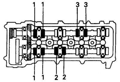
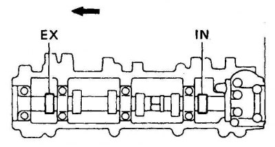
On 4-cylinder engines, check the valve clearances of cylinder 1, exhaust valves of cylinder 3, and intake valves of cylinder 2.
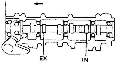
Checking the gap between the camshaft cam and the valve using a feeler gauge
The probe should pass under a little effort.
1. Measure the valve clearances with a feeler gauge. Write down those results that differ from the norm.
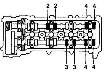
2. Rotate the crankshaft 360°and align the marks. Check clearances of other valves.
3.0L V6 engines
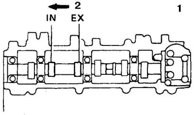
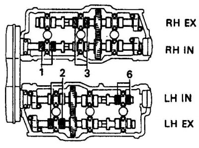
1. Set the piston of the 1st cylinder to the TDC of the compression stroke and measure the gaps of the exhaust valve of the 2nd cylinder and the inlet valve of the 6th cylinder with a feeler gauge (IN - intake, EX - exhaust). Write down those results that differ from the norm.
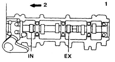
2. Rotate the crankshaft 120°and check the clearances of the intake valve of the 1st cylinder and the exhaust valve of the 3rd cylinder (1 - right side, 2 - to the front of the engine, IN - intake, EX - exhaust).
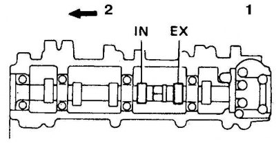
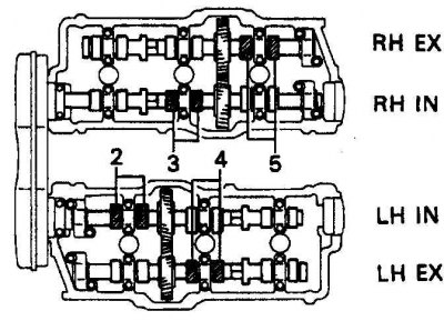
3. Turning the crankshaft another 120°, check the clearances of the inlet valve of the 2nd cylinder and the exhaust valve of the 4th cylinder (1 - left side, 2 - to the front of the engine, IN - intake, EX - exhaust).
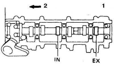
4. Further turning the crankshaft 120°, check the gaps of the inlet valve of the 3rd cylinder and the exhaust valve of the 5th cylinder (1 - right side, 2 - to the front of the engine, IN - intake, EX - exhaust).
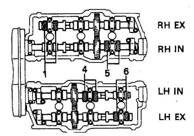
5. Rotate the crankshaft 120°, check the gaps of the inlet valve of the 4th cylinder and the exhaust valve of the 6th cylinder (1 - left side, 2 - to the front of the engine, IN - intake, EX - exhaust).
6. Rotate the crankshaft 120°, check the gaps of the inlet valve of the 5th cylinder and the exhaust valve of the 1st cylinder (IN - intake, EX - exhaust).
3.4L V6 engines
1. Measure the gaps in the indicated valves with a feeler gauge (IN - intake, EX - exhaust, RH - right side, LH - left side). Write down those results that differ from the norm.
 |  |
2. Rotate the crankshaft 240° (2/3 turn) and check the gaps in the specified valves (IN - intake, EX - exhaust, RH - right side, LH - left side). Measure the clearances in the remaining valves. Label the exhaust or intake valves that were measured.
All engines
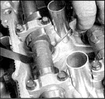
1. After measuring the clearances, turn the crankshaft so that the camshaft cam of the first adjustable valve is facing away from the shim.
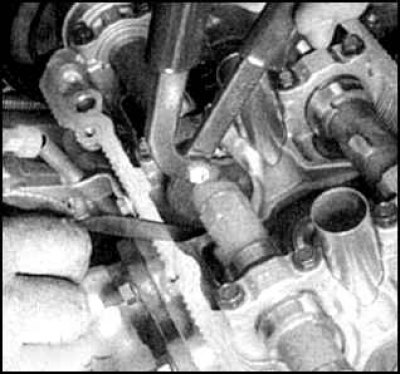
2. Align the groove on the pusher so that it faces the spark plug. Install the fixture and press the pusher by squeezing the handles of the fixture's tongs. Insert tool holder and remove pliers (you can bring the handles together and fix them with a hook without using the holder).
 | 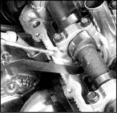 |
3. Squeezing the pusher with the holder, remove the shims by prying them with a screwdriver or magnetic tweezers.
Attention! On V6 engines of 3.4 liters, washers of the 1st and 6th cylinders are more difficult to get. Therefore tilt the tool slightly away from the intake camshaft.
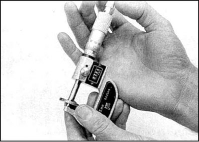
4. Using a micrometer, measure the thickness of the removed shim, then use the formula to determine the required thickness of the spacer (T is the thickness of the removed gasket, A is the measured clearance, N is the required thickness of the new gasket, V is the standard clearance):N=T (A-V).
5. The manufacturer supplies spare parts with shims of 17 size groups with a thickness of 2.500 mm to 3.300 mm in increments of 0.050 mm. Select the washer so that its thickness is as close as possible to the calculated one.
Attention! In order to save money, you can install a washer of a suitable thickness, removed from the adjacent valve.
6. Wring out a pusher the adaptation and establish a new washer. Check clearance.
7. Repeat the above procedure for the rest of the valves. Install all removed parts in reverse order.
Thickness of shims supplied as spares
| Washer number | New gasket thickness, mm | Washer number | New gasket thickness, mm |
| 1 | 2,500 | 10 | 2,950 |
| 2 | 2,550 | 11 | 3,000 |
| 3 | 2,600 | 12 | 3,050 |
| 4 | 2,650 | 13 | 3,100 |
| 5 | 2,700 | 14 | 3,150 |
| 6 | 2,750 | 15 | 3,200 |
| 7 | 2,800 | 16 | 3,250 |
| 8 | 2,850 | 17 | 3,300 |
| 9 | 2,900 |