
Examination
4-cylinder engines
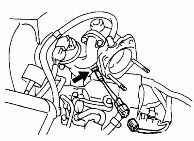
The location of the checked valves of the recirculation system on a 4-cylinder engine
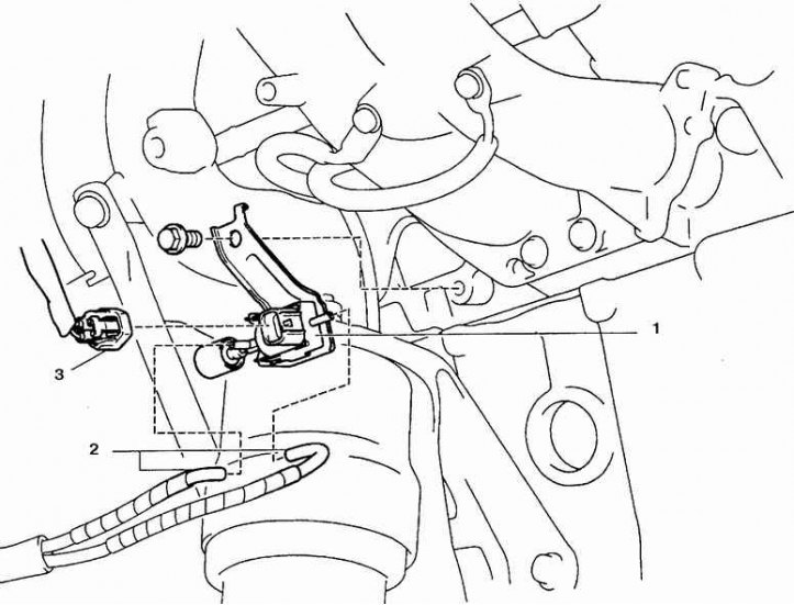
1. Pneumatic distributor of the recirculation valve; 2. Hose; 3. Pneumatic distributor connector on the recirculation valve
Recirculation valve
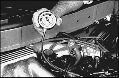
1. Start the engine, disconnect the hose from the valve and attach the vacuum pump in its place.
2. When creating a vacuum in the valve, the engine should become unstable, and the vacuum gauge reading should not fluctuate. If not, check suction manifold for cleanliness or replace valve.
Pilot valve filter
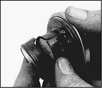
1. Remove the valve cap.

2. Remove the control valve and take out the filters. The rough surface of the outer filter must face outwards. Blow out filters and replace.
Recirculation system
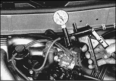
1. Disconnect the hose from the recirculation valve and install a vacuum gauge between the valve and the pneumatic distributor.
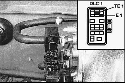
2. Start the engine and connect conclusions TE1 and E1 on a diagnostic socket.
At an engine temperature of 55°C and 2500 rpm, there should be no vacuum.
On a warm engine at 2500 rpm, there should be a slight vacuum.
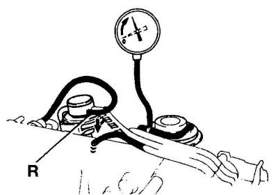
3. Connect connection R to the suction manifold with a piece of hose. At 2500 rpm there should be a significant underpressure.
4. Check the resistance of the pneumatic distributor, which should be 33-39 ohms (see fig. The location of the checked valves of the recirculation system on a 4-cylinder engine). Otherwise, replace the air distributor.
6-cylinder engines
Recirculation valve
The test procedure is the same as described above for a 4-cylinder engine.
Temperature sensor
Disconnect connector (temperature sensor of the recirculation system screwed into the intake pipe) and check the resistance of the sensor at different temperatures (see subsection 7.2.2.).
Recirculation valve position sensor
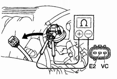
Disconnect the connector and check the resistance of the sensor (see subsection 7.2.2.). To check the resistance of the recirculation valve position sensor, connect an ohmmeter to terminals E2 and VC.
Pneumatic distributor
The location of the pneumatic valve on the V6 engine
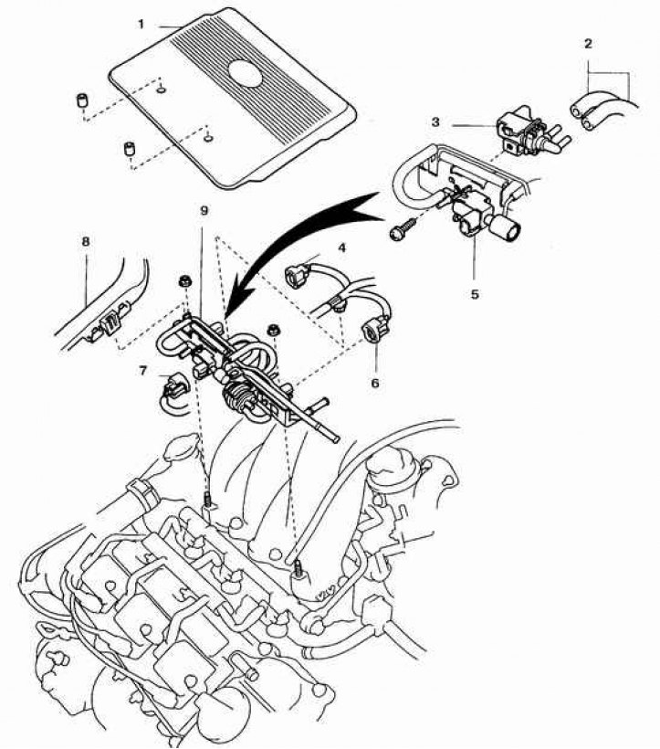
1. Lid; 2. Hoses; 3. Pneumatic distributor of the gasoline vapor recovery system; 4, 6, 7. Connectors; 5. Pneumatic distributor of ACIS system; 8. Chute of high-voltage wires; 9. Valves of the gasoline vapor recovery system
Replacement
Recirculation valve
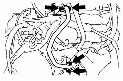 | 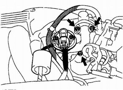 |
Disconnect the hose and tube from the valve (on V6 engines). See fig. left. Turn away bolts (indicated by arrows in Fig. on right) and remove the valve.
Installing the recirculation valve
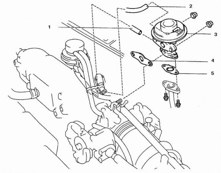
1, 2. Hose; 3. Valve; 4, 5. Gasket
Control valve
Label and disconnect hoses. Remove the control valve from the bracket.